Nissan Versa (N17): Combination switch input circuit
Diagnosis Procedure
Regarding Wiring Diagram information, refer to BCS "Wiring Diagram".
1.CHECK INPUT 1 - 5 CIRCUIT FOR OPEN
1. Turn ignition switch OFF.
2. Disconnect BCM and combination switch connectors.
3. Check continuity between BCM connector and combination switch connector.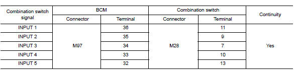
Is the inspection result normal?
YES >> GO TO 2.
NO >> Repair harness or connectors.
2.CHECK INPUT 1 - 5 CIRCUIT FOR SHORT
Check for continuity between BCM connector and ground.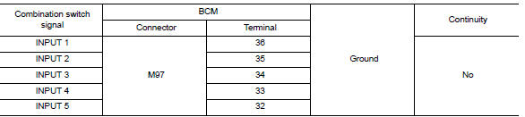
Is the inspection result normal?
YES >> Repair harness or connectors.
NO >> GO TO 3.
3.CHECK BCM OUTPUT VOLTAGE
1. Connect BCM connector.
2. Check voltage between BCM connector and ground.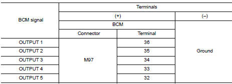
Is the inspection result normal?
YES >> Replace combination switch.
NO >> Replace BCM. Refer to BCS "Removal and Installation".
 Power supply and ground circuit
Diagnosis Procedure Regarding Wiring Diagram information, refer to BCS "Wiring Diagram". 1.CHECK FUSES AND FUSIBLE LINK Is the fuse blown? YES >> Replace the blown fuse or fusible ...
Combination switch output circuit
Diagnosis Procedure Regarding Wiring Diagram information, refer to BCS "Wiring Diagram". 1.CHECK OUTPUT 1 - 5 CIRCUIT FOR OPEN 1. Turn ignition switch OFF. 2. Disconnect BCM and combinat ...
Other materials:
P1715 Input speed sensor
Description
ECM receives input speed sensor signal from TCM via the CAN communication
line. ECM uses this signal for
engine control.
DTC Logic
DTC DETECTION LOGIC
NOTE:
If DTC P1715 is displayed with DTC UXXXX, first perform the
trouble diagnosis for DTC UXXXX.
If DTC P1715 is displa ...
Service data and specifications
(SDS)
General Specification
CAUTION:
Use only Genuine NISSAN Matic S ATF. Do not mix with other ATF.
Using ATF other than Genuine NISSAN Matic S ATF will cause
deterioration of driveability and A/T durability, and may damage
the A/T, which is not covered by the warranty.
*1: ...
Categories
- Manuals Home
- Nissan Versa Owners Manual
- Nissan Versa Service Manual
- Video Guides
- Questions & Answers
- External Resources
- Latest Updates
- Most Popular
- Sitemap
- Search the site
- Privacy Policy
- Contact Us

0.0064