Nissan Versa (N17): Combination switch output circuit
Diagnosis Procedure
Regarding Wiring Diagram information, refer to BCS "Wiring Diagram".
1.CHECK OUTPUT 1 - 5 CIRCUIT FOR OPEN
1. Turn ignition switch OFF.
2. Disconnect BCM and combination switch connectors.
3. Check continuity between BCM connector and combination switch connector.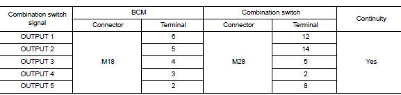
Is the inspection result normal?
YES >> GO TO 2.
NO >> Repair harness or connectors.
2.CHECK OUTPUT 1 - 5 CIRCUIT FOR SHORT
Check for continuity between BCM connector and ground.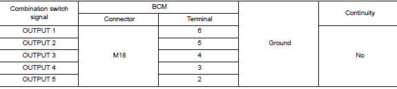
Is the inspection result normal?
YES >> Repair harness or connectors.
NO >> GO TO 3.
3.CHECK BCM INPUT SIGNAL
1. Connect BCM and combination switch connectors.
2. Turn ON any switch in the system that is malfunctioning.
3. Check voltage between BCM connector and ground.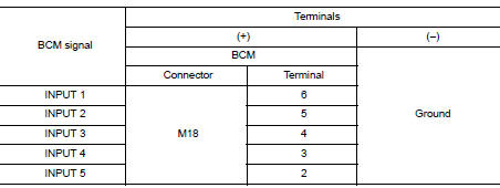
Is the inspection result normal?
Yes >> Replace BCM. Refer to BCS "Removal and Installation".
No >> Replace combination switch.
SYMPTOM DIAGNOSIS
COMBINATION SWITCH SYSTEM SYMPTOMS
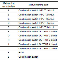
Symptom Table
1. Perform the data monitor of CONSULT to check for any malfunctioning item.
2. Check the malfunction combinations.
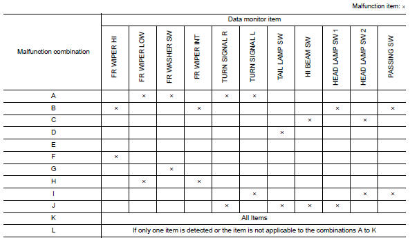
3. Identify the malfunctioning part from the agreed combination and repair or replace the part.
REMOVAL AND INSTALLATION
 Combination switch input circuit
Diagnosis Procedure Regarding Wiring Diagram information, refer to BCS "Wiring Diagram". 1.CHECK INPUT 1 - 5 CIRCUIT FOR OPEN 1. Turn ignition switch OFF. 2. Disconnect BCM and combina ...
BCM (Body control module)
Removal and Installation CAUTION: Before replacing BCM, perform "READ CONFIGURATION" to save or print current vehicle specification. Refer to BCS "ADDITIONAL SERVICE WHEN REPLACING CONTR ...
Other materials:
P0976 Shift solenoid B
DTC Logic
DTC DETECTION LOGIC
DTC
Trouble diagnosis name
DTC detection condition
Possible causes
P0976
Shift Solenoid B Control Circuit
Low
The following diagnosis conditions
are met, and the TCM low
clutch solenoid valve current
monitor reading is 200 m ...
P062F EEPROM
Description
TCM compares the calculated value stored in the flash ROM with the value
stored in TCM. If the calculated
value does not agree with the stored value, TCM judges this as a malfunction.
DTC Logic
DTC DETECTION LOGIC
DTC
Trouble diagnosis name
DTC detection condition
...
Categories
- Manuals Home
- Nissan Versa Owners Manual
- Nissan Versa Service Manual
- Video Guides
- Questions & Answers
- External Resources
- Latest Updates
- Most Popular
- Sitemap
- Search the site
- Privacy Policy
- Contact Us

0.0056