Nissan Versa (N17): Combination switch input circuit
Diagnosis Procedure
Regarding Wiring Diagram information, refer to BCS "Wiring Diagram".
1.CHECK INPUT 1 - 5 CIRCUIT FOR OPEN
1. Turn ignition switch OFF.
2. Disconnect BCM and combination switch connectors.
3. Check continuity between BCM connector and combination switch connector.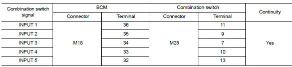
Is the inspection result normal?
YES >> GO TO 2.
NO >> Repair harness or connectors.
2.CHECK INPUT 1 - 5 CIRCUIT FOR SHORT
Check for continuity between BCM connector and ground. 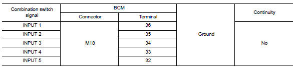
Is the inspection result normal?
YES >> Repair harness or connectors.
NO >> GO TO 3.
3.CHECK BCM OUTPUT VOLTAGE
1. Connect BCM connector.
2. Check voltage between BCM connector and ground.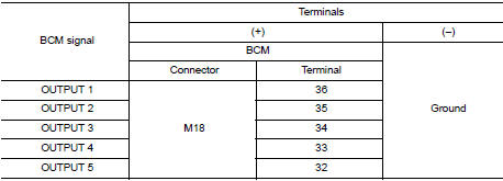
Is the inspection result normal?
YES >> Replace combination switch.
NO >> Replace BCM. Refer to BCS "Removal and Installation".
 Power supply and ground circuit
Diagnosis Procedure Regarding Wiring Diagram information, refer to BCS "Wiring Diagram". 1.CHECK FUSES AND FUSIBLE LINK Check that the following fuses and fusible link are not blown. ...
Combination switch output circuit
Diagnosis Procedure Regarding Wiring Diagram information, refer to BCS "Wiring Diagram". 1.CHECK OUTPUT 1 - 5 CIRCUIT FOR OPEN 1. Turn ignition switch OFF. 2. Disconnect BCM and combinat ...
Other materials:
Interior lights
The interior light has a three-position switch and
operates regardless of ignition switch position.
When the switch is in the ON position 1 , the
interior lights illuminate, regardless of door position.
The lights will go off after a period of time
unless the ignition switch is placed i ...
P0506 ISC system
Description
The ECM controls the engine idle speed to a specified level through the fine
adjustment of the air, which is let
into the intake manifold, by operating the electric throttle control actuator.
The operating of the throttle valve is
varied to allow for optimum control of the engine ...
Categories
- Manuals Home
- Nissan Versa Owners Manual
- Nissan Versa Service Manual
- Video Guides
- Questions & Answers
- External Resources
- Latest Updates
- Most Popular
- Sitemap
- Search the site
- Privacy Policy
- Contact Us

0.0056