Nissan Versa (N17): Push-button ignition switch
Component Function Check
1.CHECK FUNCTION
1. Select "PUSH SW" in "Data Monitor" of BCM with CONSULT.
2. Check the push-button ignition switch signal under the following
conditions.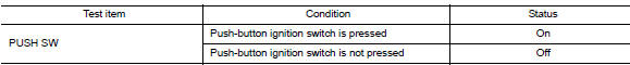
Is the indication normal?
YES >> Inspection End.
NO >> Go to PCS "Diagnosis Procedure".
Diagnosis Procedure
Regarding Wiring Diagram information, refer to PCS "Wiring Diagram".
1. CHECK PUSH-BUTTON IGNITION SWITCH OUTPUT SIGNAL (PUSH-BUTTON IGNITION SWITCH)
1. Turn ignition switch OFF.
2. Disconnect push-button ignition switch connector and IPDM E/R connector E47.
3. Check voltage between push-button ignition switch connector M25 terminal 8
and ground.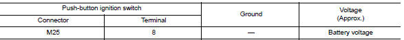
Is the inspection result normal?
YES >> GO TO 3.
NO >> GO TO 2.
2. CHECK PUSH-BUTTON IGNITION SWITCH CIRCUIT (BCM)
1. Disconnect BCM connector M98.
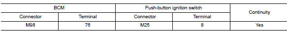
2. Check continuity between BCM connector M98 terminal 76 and push-button
ignition switch connector
M25 terminal 8.
3. Check continuity between BCM connector M98 terminal 76 and ground.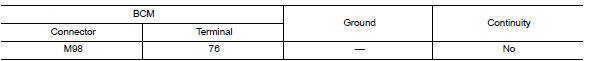
Is the inspection result normal?
YES >> Replace BCM. Refer to BCS "Removal and Installation".
NO >> Repair or replace harness or connectors.
3. CHECK IGNITION SWITCH OUTPUT SIGNAL (IPDM E/R)
Check voltage between IPDM E/R connector E47 terminal 81 and ground.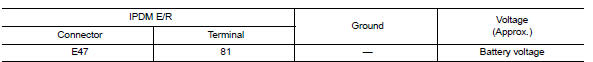
Is the inspection result normal?
YES >> GO TO 5.
NO >> GO TO 4.
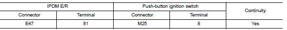
4. CHECK PUSH-BUTTON IGNITION SWITCH CIRCUIT (IPDM E/R)
1. Disconnect BCM connector M17.
2. Check continuity between IPDM E/R connector E47 terminal 81 and
push-button ignition switch connector
M25 terminal 8.
3. Check continuity between IPDM E/R connector E47 terminal 81 and ground.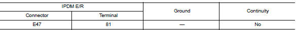
Is the inspection result normal?
YES >> Replace IPDM E/R. Refer to PCS"Removal and Installation".
NO >> Repair or replace harness or connectors.
5.CHECK PUSH-BUTTON IGNITION SWITCH GROUND CIRCUIT
Check continuity between push-button ignition switch connector M25 terminal 4
and ground.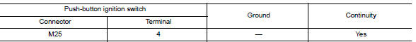
Is the inspection result normal?
YES >> GO TO 6.
NO >> Repair or replace harness or connectors.
6.CHECK PUSH-BUTTON IGNITION SWITCH
Refer to PCS "Component Inspection".
Is the inspection result normal?
YES >> Refer to GI"Intermittent Incident".
NO >> Replace push-button ignition switch.
Component Inspection
1.CHECK PUSH-BUTTON IGNITION SWITCH
1. Turn ignition switch OFF.
2. Disconnect push-button ignition switch connector.
3. Check continuity between push-button ignition switch terminals.
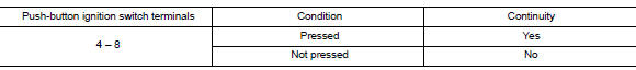
Is the inspection result normal?
YES >> Inspection End.
NO >> Replace push-button ignition switch.
SYMPTOM DIAGNOSIS
 B26F6 BCM
Other materials:
Precautions
Precaution for Supplemental Restraint System
(SRS) "AIR BAG" and "SEAT BELT PRE-TENSIONER"
The Supplemental Restraint System such as "AIR BAG" and "SEAT BELT PRE-TENSIONER",
used along
with a front seat belt, helps to reduce the risk or severity of injury to the
driver and ...
A/T Shift lock system
A/T Shift lock system : component parts
location
1 Stop lamp switch. 2 Shift lock release lever. 3 Park position switch.
4 Shift lock solenoid.
A/T Shift lock system : component description
...
Categories
- Manuals Home
- Nissan Versa Owners Manual
- Nissan Versa Service Manual
- Video Guides
- Questions & Answers
- External Resources
- Latest Updates
- Most Popular
- Sitemap
- Search the site
- Privacy Policy
- Contact Us

0.0064