Nissan Versa (N17): G Sensor
Exploded View
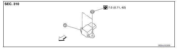
1. G sensor
![]() Front
Front
Removal and Installation
CAUTION:
- Do not drop or strike G sensor, because it may be damaged by impact.
- Do not use a power tool.
REMOVAL
- Disconnect the battery negative terminal. Refer to PG "Removal and Installation".
- Remove center console. Refer to IP "Removal and Installation".
- Disconnect the harness connector from G sensor.
- Remove G sensor.
INSTALLATION
Installation is in the reverse order of removal.
Adjustment
ADJUSTMENT AFTER INSTALLATION
Perform "G SENSOR CALIBRATION". Refer to TM "Description".
 Air breather hose
Removal and Installation REMOVAL Remove air duct (inlet). Refer to EM "Exploded View". Remove air breather hose from transaxle assembly. INSTALLATION Installation is in the reve ...
Oil pan
Exploded View 1. Transaxle assembly 2. Oil pan gasket 3. Magnet 4. Oil pan 5. Overflow tube 6. Drain plug gasket 7. Drain plug 8. Oil pan fitting bolt Removal and Installation REMOVAL R ...
Other materials:
Child safety
WARNING
Do not allow children to play with the seat
belts. Most seating positions are
equipped with Automatic Locking Retractor
(ALR) mode seat belts. If the seat belt
becomes wrapped around a child's neck
with the ALR mode activated, the child can
be seriously injured or killed if the seat
...
Precautions
Precaution for Supplemental Restraint System
(SRS) "AIR BAG" and "SEAT BELT PRE-TENSIONER"
The Supplemental Restraint System such as "AIR BAG" and "SEAT BELT PRE-TENSIONER",
used along
with a front seat belt, helps to reduce the risk or severity of injury to the
driver and ...
Categories
- Manuals Home
- Nissan Versa Owners Manual
- Nissan Versa Service Manual
- Video Guides
- Questions & Answers
- External Resources
- Latest Updates
- Most Popular
- Sitemap
- Search the site
- Privacy Policy
- Contact Us

0.0045