Nissan Versa (N17): Air breather hose
Removal and Installation
REMOVAL
- Remove air duct (inlet). Refer to EM "Exploded View".
- Remove air breather hose from transaxle assembly.
INSTALLATION
Installation is in the reverse order of removal.
CAUTION:
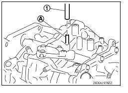
- Check that air breather hose is not collapsed or blocked due to folding or bending when installed.
- Be sure to insert air breather hose (1) fully until it reaches the base of the transaxle tube (A).
 TCM
TCM
Exploded View 1. TCM 2. Bracket 3. Clip Front Removal and Installation CAUTION: When replacing TCM, note the "CVTF DETERIORATION DATE" value displayed on CONSULT "CONFORM CVTF DETERIORTN" ...
G Sensor
Exploded View 1. G sensor Front Removal and Installation CAUTION: Do not drop or strike G sensor, because it may be damaged by impact. Do not use a power tool. REMOVAL Di ...
Other materials:
Preparation
Special Service Tools
The actual shapes of KentMoore tools may differ from those of special
service tools illustrated here.
Tool number
(KentMoore No.)
Tool name
Description
KV10111100
(J37228)
Seal cutter
Removing oil pan (lower and upper) etc.
...
Water pump
Exploded View
1. Gasket 2. Water pump 3. Water pump pulley
Removal and Installation
REMOVAL
CAUTION:
Do not remove the radiator cap when the engine is hot. Serious burns
could occur from highpressure
engine coolant escaping from the radiator. Wrap a thick cloth around the
radiator cap. ...
Categories
- Manuals Home
- Nissan Versa Owners Manual
- Nissan Versa Service Manual
- Video Guides
- Questions & Answers
- External Resources
- Latest Updates
- Most Popular
- Sitemap
- Search the site
- Privacy Policy
- Contact Us

0.0046