Nissan Versa (N17): Component parts
CVT CONTROL SYSTEM
CVT CONTROL SYSTEM : Component Parts Location
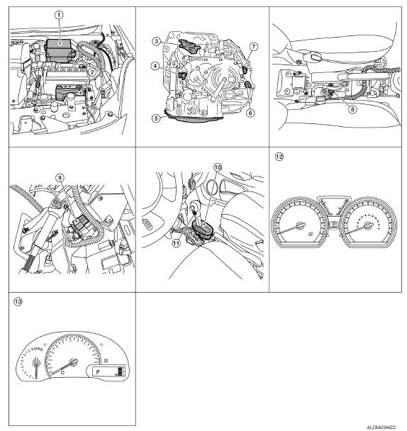
1. IPDM E/R 2. TCM 3. Transmission range switch 4. Primary speed sensor 5. CVT unit 6. Output speed sensor 7. Secondary speed sensor 8. G sensor 9. Stop lamp switch 10. CVT shift selector 11. Overdrive control switch 12. Combination meter (type A) 13. Combination meter (type B)
COMPONENT DESCRIPTION
| Component | Function | |
| IPDM E/R | The TCM receives the A/C compressor feedback signal via CAN communications from the IPDM E/R. | |
| TCM | TM "CVT CONTROL SYSTEM : TCM" | |
| Transmission range switch | TM "CVT CONTROL SYSTEM : Transmission Range Switch" | |
| Primary speed sensor | TM "CVT CONTROL SYSTEM : Primary Speed Sensor" | |
|
CVT unit |
- |
|
| Control valve | ROM assembly* | TM "CVT CONTROL SYSTEM : ROM Assembly" |
| CVT fluid temperature sensor* | TM "CVT CONTROL SYSTEM : CVT Fluid Temperature Sensor" | |
| Secondary pressure sensor* | TM "CVT CONTROL SYSTEM : Secondary Pressure Sensor" | |
| Primary pressure solenoid valve* | TM "CVT CONTROL SYSTEM : Primary Pressure Solenoid Valve" | |
| Low brake solenoid valve* | TM "CVT CONTROL SYSTEM : Low Brake Solenoid Valve" | |
| High clutch & reverse brake solenoid valve* | TM "CVT CONTROL SYSTEM : High Clutch & Reverse Brake Solenoid Valve" | |
| Torque converter clutch solenoid valve* | TM "CVT CONTROL SYSTEM : Torque Converter Clutch Solenoid Valve" | |
| Line pressure solenoid valve* | TM "CVT CONTROL SYSTEM : Line Pressure Solenoid Valve" | |
| Output speed sensor | TM "CVT CONTROL SYSTEM : Output Speed Sensor" | |
| Secondary speed sensor | TM "CVT CONTROL SYSTEM : Secondary Speed Sensor" | |
| G sensor | TM "CVT CONTROL SYSTEM : G Sensor" | |
| Overdrive control switch | TM "CVT CONTROL SYSTEM : Overdrive Control Switch" | |
| Combination meter | The TCM receives the sport mode switch signal via CAN communications from the combination meter. | |
| ABS actuator and electric unit (control unit) | The TCM receives the following signals via CAN
communications from the ABS
actuator and electric unit (control unit).
|
|
| ECM | For purposes including improving the feeling when
shifting and preventing
drops in engine speed, control signals are exchanged between the ECM and
TCM, and real-time cooperative control is performed according to the
vehicle
driving conditions. (Engine and CVT integrated control) - Engine and CVT integrated control signal - The TCM receives the following signals via CAN communications from the ECM. - Engine speed signal - Accelerator pedal position signal - Closed throttle position signal - TCM sends and receives the following signals with ECM through CAN communication to perform D position N idle control. - N idle instruction signal |
|
| BCM | The TCM receives the following signals via CAN
communications from the
BCM. - Stop lamp switch signal - Turn indicator signal |
|
*: These components are included in control valve assembly.
CVT CONTROL SYSTEM : TCM
- The vehicle driving status is judged based on the signals from the sensors, switches, and other control units, and the optimal transaxle control is performed.
- For TCM control items, refer to TM "CVT CONTROL SYSTEM : System Description".
CVT CONTROL SYSTEM : ROM Assembly
- The ROM assembly is installed to control valve.
- The ROM assembly stores the calibration data (characteristic value) of each solenoid valve. TCM enables accurate hydraulic control by obtaining the calibration data.
CVT CONTROL SYSTEM : Transmission Range Switch
- The transmission range switch is installed to upper part of transaxle case.
- The transmission range switch detects the selector lever position.
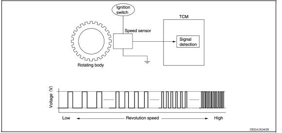
CVT CONTROL SYSTEM : Primary Speed Sensor
- The primary speed sensor is installed to side cover of transaxle.
- The primary speed sensor detects primary pulley speed.
- The primary speed sensor generates the ON-OFF pulse (short waveform) in proportion to the rotating body speed which is "The higher the rotating body speed is, the faster the change cycle is". The TCM judges the rotating speed from the changing cycle of this pulse signal

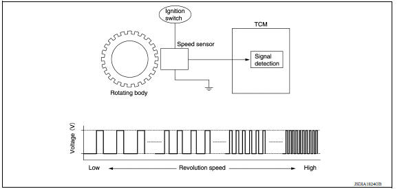
CVT CONTROL SYSTEM : Secondary Speed Sensor
- The secondary speed sensor is installed to side cover of transaxle.
- The secondary speed sensor detects secondary pulley speed.
- The secondary speed sensor generates the ON-OFF pulse (short waveform) in proportion to the rotating body speed which is "The higher the rotating body speed is, the faster the change cycle is". The TCM judges the rotating speed from the changing cycle of this pulse signal.
CVT CONTROL SYSTEM : Output Speed Sensor
- The output speed sensor is installed to the back side of transaxle case.
- The output speed sensor detects final gear speed. TCM evaluates the vehicle speed from the final gear revolution.
- The output speed sensor generates the ON-OFF pulse (short waveform) in proportion to the rotating body speed which is "The higher the rotating body speed is, the faster the change cycle is". The TCM judges the rotating speed from the changing cycle of this pulse signal.
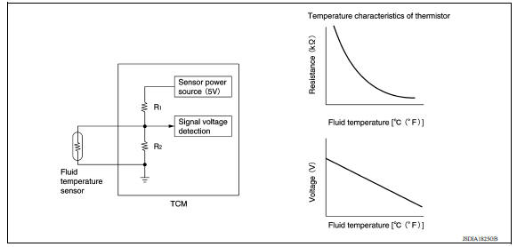
CVT CONTROL SYSTEM : CVT Fluid Temperature Sensor
- The CVT fluid temperature sensor is installed to control valve.
- The CVT fluid temperature sensor detects CVT fluid temperature in oil pan.
- The fluid temperature sensor uses a thermistor, and changes the signal voltage by converting changes in the CVT fluid temperature to a resistance value. TCM evaluates the CVT fluid temperature from the signal voltage value.
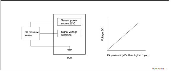
CVT CONTROL SYSTEM : Secondary Pressure Sensor
- The secondary pressure sensor is installed to control valve.
- The secondary pressure sensor detects the pressure applied to the secondary pulley.
- When pressure is applied to the ceramic device in the secondary pressure sensor, the ceramic device is deformed, resulting in voltage change. TCM evaluates the secondary pressure from its voltage change. Voltage is increased along with pressure increase.
CVT CONTROL SYSTEM : Primary Pressure Solenoid Valve
- The primary pressure solenoid valve is installed to control valve.
- The primary pressure solenoid valve controls the primary pressure control valve. For information about the primary pressure control valve, refer to TM "TRANSAXLE : Component Description".
- The primary pressure solenoid valve uses the linear solenoid valve [N/H (normal high) type].
NOTE:
- The principle of the linear solenoid valve utilizes the fact that the force pressing on the valve spool installed inside the coil increases nearly in proportion to the current. This allows it to produce a fluid pressure that is proportional to this pressing force.
- The N/H (normal high) produces hydraulic control when the coil is not energized.
CVT CONTROL SYSTEM : Low Brake Solenoid Valve
- The low brake solenoid valve is installed to control valve.
- The low brake solenoid valve adjusts the tightening pressure of the low brake.
- The low brake solenoid valve uses the linear solenoid valve [N/L (normal low) type].
NOTE:
- The principle of the linear solenoid valve utilizes the fact that the force pressing on the valve spool installed inside the coil increases nearly in proportion to the current. This allows it to produce a fluid pressure that is proportional to this pressing force.
- The N/L (normal low) type does not produce hydraulic control when the coil is not energized.
CVT CONTROL SYSTEM : High Clutch & Reverse Brake Solenoid Valve
- The high clutch & reverse brake solenoid valve is installed to control valve.
- The high clutch & reverse brake solenoid valve adjusts the tightening pressure of the high clutch and reverse brake.
- The high clutch & reverse brake solenoid valve uses the linear solenoid valve [N/H (normal high) type].
NOTE:
- The principle of the linear solenoid valve utilizes the fact that the force pressing on the valve spool installed inside the coil increases nearly in proportion to the current. This allows it to produce a fluid pressure that is proportional to this pressing force.
- The N/H (normal high) produces hydraulic control when the coil is not energized.
CVT CONTROL SYSTEM : Torque Converter Clutch Solenoid Valve
- The torque converter clutch solenoid valve is installed to control valve.
- The torque converter clutch solenoid valve controls the torque converter clutch control valve. For information about the torque converter clutch control valve, refer to TM "TRANSAXLE : Component Description".
- The torque converter clutch solenoid valve utilizes a linear solenoid valve [N/L (normal low) type].
NOTE:
- The principle of the linear solenoid valve utilizes the fact that the force pressing on the valve spool installed inside the coil increases nearly in proportion to the current. This allows it to produce a fluid pressure that is proportional to this pressing force.
- The N/L (normal low) type does not produce hydraulic control when the coil is not energized.
CVT CONTROL SYSTEM : Line Pressure Solenoid Valve
The line pressure solenoid valve is installed to control valve.
- The line pressure solenoid valve controls the pressure regulator valve. For information about the pressure regulator valve, refer to TM "TRANSAXLE : Component Description".
- The line pressure solenoid valve uses the linear solenoid valve [N/H (normal high) type].
NOTE:
- The principle of the linear solenoid valve utilizes the fact that the force pressing on the valve spool installed inside the coil increases nearly in proportion to the current. This allows it to produce a fluid pressure that is proportional to this pressing force.
- The N/H (normal high) produces hydraulic control when the coil is not energized.
CVT CONTROL SYSTEM : G Sensor
- G sensor is installed to floor under instrument lower cover.
- G sensor detects front/rear G and inclination applied to the vehicle.
- G sensor converts front/rear G and inclination applied to the vehicle to voltage signal. TCM evaluates front/ rear G and inclination angle of the vehicle from the voltage signal.
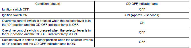
CVT CONTROL SYSTEM : Overdrive Control Switch
The overdrive control switch is installed to the selector lever knob.
- When the OD OFF indicator lamp on the combination meter is OFF and the overdrive control switch is pressed, the overdrive is cancelled and the OD OFF indicator lamp is ON.
- When the OD OFF indicator lamp on the combination meter is ON and the overdrive control switch is pressed, the overdrive is active and the OD OFF indicator lamp is OFF.
CVT CONTROL SYSTEM : OD OFF Indicator Lamp
OD OFF indicator lamp is positioned on the combination meter.
- OD OFF indicator lamp is ON when set to the overdrive off.
- OD OFF indicator lamp turns on for a certain period of time when the
ignition switch turns ON, and then turns
off.
CVT CONTROL SYSTEM : Shift Position Indicator
TCM transmits shift position signal to combination meter via CAN communication. The actual shift position is displayed on combination meter according to the signal.
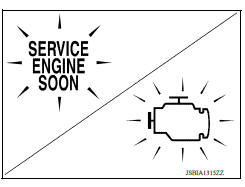
CVT CONTROL SYSTEM : Malfunction Indicator Lamp (MIL)
The malfunction indicator lamp (MIL) is located on the combination meter.
The MIL will illuminate when the ignition switch is turned ON without the engine running. This is a bulb check.
When the engine is started, the MIL should turn off. If the MIL remains illuminated, the on board diagnostic system has detected an engine system malfunction.
For details, refer to EC "DIAGNOSIS DESCRIPTION : Malfunction Indicator Lamp (MIL)".
 Precautions
Shift lock system
SHIFT LOCK SYSTEM : Component Parts Location 1. Stop lamp switch 2. Shift lock release lever 3. Park position switch 4. Shift lock solenoid Component Function Stop lamp switc ...
Other materials:
P0743 Torque converter
DTC Logic
DTC DETECTION LOGIC
DTC
Trouble diagnosis name
DTC detection condition
Possible causes
P0743
Torque Converter Clutch Circuit
Electrical
The following diagnosis conditions
are met, and the TCM
torque converter clutch solenoid
valve current monito ...
Hood lock secondary control
HOOD LOCK SECONDARY CONTROL : Removal
and Installation
REMOVAL
Remove radiator upper seal clips and then remove upper clip from
radiator side seal (RH). Refer to DLK "Exploded View".
Remove hood lock secondary control nuts and hood lock secondary control.
INSTALLATION
Instal ...
Categories
- Manuals Home
- Nissan Versa Owners Manual
- Nissan Versa Service Manual
- Video Guides
- Questions & Answers
- External Resources
- Latest Updates
- Most Popular
- Sitemap
- Search the site
- Privacy Policy
- Contact Us

0.0056