Nissan Versa (N17): Control linkage
Exploded View
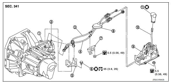
1. Shifter lever A 2. Selector lever 3. Selector cable 4. Shifter cable 5. Cable mounting bracket 6. Tapping bolt 7. Bracket 8. Grommet 9. M/T shift selector assembly 10. Shift selector 11. Shift selector handle
Removal and Installation
REMOVAL
- Move the shift selector to the neutral position.
- Remove the battery tray. Refer to PG, "Removal and Installation".
- Pull out and disconnect cables from shifter lever A and selector lever, using a suitable tool.
- While pressing the lock of the selector cable in the direction of the arrows shown, remove the selector cable from the cable mounting bracket.
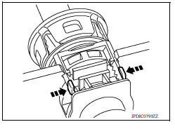
- While pressing the lock of the shifter cable in the direction of the arrows shown, remove the shifter cable from the cable mounting bracket.
- Remove cable mounting bracket from clutch housing.
- Pull the shift selector handle upward to remove.
- Remove center console assembly. Refer to IP, "Removal and Installation".
- Pull out and disconnect each cable from the M/T shift selector assembly, using a suitable tool.
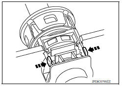
a. While pressing the lock of the selector cable in the direction of the arrows shown, remove the selector cable from the M/T shift selector assembly.
b. While pressing the lock of the shifter cable in the direction of the arrows shown, remove the shifter cable from the M/T shift selector assembly.
- Remove the M/T shift selector assembly.
- Remove center muffler, exhaust front tube, and heat plate. Refer to EX, "Removal and Installation".
- Remove the bracket from the vehicle.
- Remove the grommet and then remove the shifter cable and selector cable from the vehicle.
INSTALLATION
Installation is in the reverse order of removal.
CAUTION:
- Install each cable without causing interference with other parts. Do not allow cable to bend less than 120 mm (4.72 in), or exceed 180 degree twist.
- Install boot of each cable without causing interference with other parts. Do not exceed 90 degree twist.
- Fit boot to center console assembly and the groove on shift selector handle.
- To install the shift selector handle, press it onto the shift selector.
CAUTION:
- Do not reuse shift selector handle.
- Be careful with orientation of shift selector handle.
- Bolt hole is not threaded on new clutch housing. Self-tapping bolt is used to attach lock plate to clutch housing.
CAUTION: Do not reuse self-tapping bolt.
- Insert each cable until it reaches the cable mounting bracket and M/T shift selector assembly.
- Insert each cable until it reaches the shifter lever A and the selector lever.
- Move the shift selector to the neutral position.
Inspection
INSPECTION AFTER INSTALLATION
Shift Selector Handle
Check that the shift selector handle is installed in the right position.
Shifter Cable and Selector Cable
- Pull each cable in the removal direction to check that it does not disconnect from the cable mounting bracket.
- Pull each cable in the removal direction to check that it does not disconnect from the M/T shift selector assembly.
- Pull grommet in the removal direction to check that it does not
disconnect from the vehicle.
M/T Shift Selector Assembly and Shift Selector
- Check that there is no unusual noise, binding, bending, looseness, and interference when the shift selector is moved to each position. If there is a malfunction, then repair or replace the malfunctioning part.
- Check that the shift selector smoothly returns to the neutral position after moving the shift selector from 1st to 2nd gear and releasing it. If there is a malfunction, then repair or replace the malfunctioning part.
- Check that the shift selector smoothly returns to the neutral position after moving the shift selector from 5th to the reverse gear position and releasing it. If there is a malfunction, then repair or replace the malfunctioning part.
 Position switch
Removal and Installation REMOVAL Drain gear oil. Refer to TM, "Draining". Disconnect the harness connector (A) from position switch. Remove position switch from transaxle case. ...
Air breather hose
Exploded View 1. Cap 2. Air breather hose 3. 2-way connector Removal and Installation REMOVAL Remove air cleaner case. Refer to EM, "Removal and Installation". Remove air breath ...
Other materials:
Road wheel tire assembly
Adjustment
BALANCING WHEELS (ADHESIVE WEIGHT TYPE)
Preparation Before Adjustment
Remove inner and outer balance weights from the road wheel. Using releasing
agent, remove double-faced
adhesive tape from the road wheel.
CAUTION:
Be careful not scratch the road wheel during removal.
Afte ...
Passenger air bag module
Exploded View
1. Passenger air bag module 2. Instrument panel assembly
Pawl
Removal and Installation
WARNING:
Before servicing, turn ignition switch OFF, disconnect both the
battery negative and positive terminals,
then wait at least three minutes.
Always work from the side of ai ...
Categories
- Manuals Home
- Nissan Versa Owners Manual
- Nissan Versa Service Manual
- Video Guides
- Questions & Answers
- External Resources
- Latest Updates
- Most Popular
- Sitemap
- Search the site
- Privacy Policy
- Contact Us

0.0066