Nissan Versa (N17): Spiral cable
Exploded View
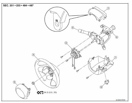
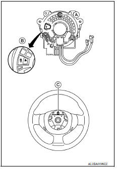
1. Steering column upper cover 2. Combination switch 3. Spiral cable
4. Steering wheel 5. Driver air bag module 6. Steering lock escutcheon
7. Steering column lower cover 8. Steering column assembly
 Pawl
Pawl
Removal and Installation
WARNING:
Always observe the following items for preventing accidental activation.
- Before servicing, turn ignition switch OFF, disconnect both battery terminals, then wait at least three minutes or more.
- Always work from the side of air bag module. Do not work in front of it.
- Do not use the air tools or electric tools for servicing.
- Always place air bag module with pad side facing upward.
- Do not cause impact to the air bag module by dropping etc. Replace the air bag module if it has been dropped or sustained an impact.
REMOVAL
- Remove the steering wheel. Refer to ST "Removal and Installation".
- Remove the steering column covers. Refer to IP "Removal and Installation".
- Disconnect the harness connectors (A) and (B) from the spiral cable body side.
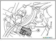
- Remove the spiral cable screws.
- Release the pawls using a suitable tool (A), then remove the spiral cable.
Pawl
CAUTION:
- Do not impact the spiral cable.
- Replace the spiral cable if it has been dropped or sustained an impact.
- Do not disassemble the spiral cable.
- Do not apply lubricant to the spiral cable.
- Do not allow oil, grease, detergent, or water to come in contact with the spiral cable.
INSTALLATION
Installation is in the reverse order of removal.
CAUTION:
- The spiral cable may snap during steering operation if the
cable is installed in an improper position.
The neutral position is set as follows.
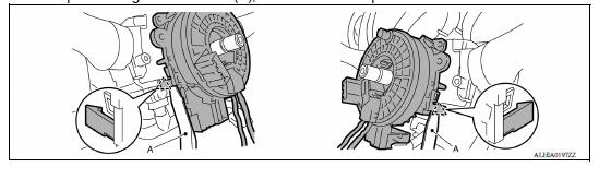
- Carefully turn the spiral cable clockwise to the end position.
Then turn it counterclockwise (about two and a half turns) and stop turning at the mark (B) where the stopper insertion holes are in the same position.
- The service part is installed in the neutral position by the stopper and can be set without adjusting after the stopper is removed.
- Do not over turn the spiral cable or go beyond the number of turns required. (This will cause the cable to snap)
- Carefully align the spiral cable locating pin (A) to the steering wheel locating pin hole (C).
- If malfunction is detected by the air bag warning lamp, after repair or replacement of the malfunctioning parts, reset the memory using self-diagnosis or CONSULT. Refer to SRC"SRS Operation Check".
- After the work is completed, check that no system malfunction is detected by air bag warning lamp.
 Driver air bag module
Exploded View 1. Driver air bag module 2. Steering wheel Removal and Installation WARNING: Always observe the following items for preventing accidental activation. Before servicing, turn ...
Passenger air bag module
Exploded View 1. Passenger air bag module 2. Instrument panel assembly Pawl Removal and Installation WARNING: Before servicing, turn ignition switch OFF, disconnect both the battery ne ...
Other materials:
Starting the engine (models without NISSAN Intelligent Key system)
1. Apply the parking brake.
2. Automatic Transmission / CVT models:
Move the shift lever to P (Park) or N (Neutral).
P (Park) is recommended.
The shift lever cannot be moved out of
P (Park) and into any of the other gear
positions if the ignition key is turned to
the OFF position or if ...
Oil filter
Removal and Installation
REMOVAL
Remove engine under cover.
Drain engine oil.
Remove oil filter using Tool (A).
: Front
Tool number : KV10115801 (J38956)
WARNING:
Be careful not to get burned; engine and engine oil may be
hot.
CAUTION:
When removing, prepare a shop cl ...
Categories
- Manuals Home
- Nissan Versa Owners Manual
- Nissan Versa Service Manual
- Video Guides
- Questions & Answers
- External Resources
- Latest Updates
- Most Popular
- Sitemap
- Search the site
- Privacy Policy
- Contact Us

0.0054