Nissan Versa (N17): Diagnosis and repair work flow
Work Flow
OVERALL SEQUENCE
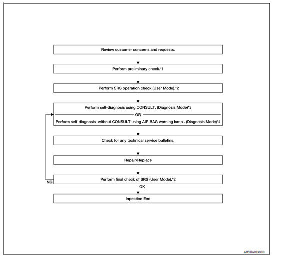
*1 SRC "Diagnosis Description" *2 SRC "SRS Operation Check" *3 SRC "Trouble Diagnosis with CONSULT" *4 SRC "Trouble Diagnosis without CONSULT"
DETAILED WORK FLOW
1.CUSTOMER INFORMATION
Get detailed information from the customer about the symptom.
>> GO TO 2
2.PRELIMINARY CHECK
Perform preliminary check. Refer to SRC "Diagnosis Description".
>> GO TO 3
3.SRS OPERATION CHECK (USER MODE)
Perform SRS operation check in User Mode. Refer to SRC "SRS Operation Check".
>> GO TO 4
4.SELF-DIAGNOSIS (DIAGNOSIS MODE)
Perform SELF-DIAGNOSIS. Refer to SRC "Trouble Diagnosis with CONSULT"or SRC"Trouble Diagnosis without CONSULT".
>> GO TO 5
5.TECHNICAL SERVICE BULLETINS
Check for technical service bulletins.
>> GO TO 6
6.REPLACE PART
Replace the malfunctioning part.
>> GO TO 7
7.FINAL CHECK
Check SRS using Diagnosis Mode and User Mode.
Does Diagnosis Mode and User Mode indicate SRS normal?
YES >> Inspection End.
NO >> GO TO 4
 Diagnosis sensor unit
DTC Index DIAGNOSTIC CODE CHART NOTE: Follow the procedures in numerical order when repairing malfunctioning parts. Confirm whether malfunction is eliminated using air bag warning lamp or CONSU ...

Other materials:
Instrument panel
1. Headlight/turn signal switch/fog light
switch (if so equipped)
2. Driver's supplemental air bag (P. 1-39)
Horn
3. Meters and gauges. Warning and indicator lights
4. Wiper and washer switch
5. Vents
6. Rear window defroster switch
7. Front passenger air bag status light
8. Hazard warn ...
Break-in schedule
CAUTION
During the first 1,200 miles (2,000 km),
follow these recommendations to obtain
maximum engine performance and ensure
the future reliability and economy of your
new vehicle. Failure to follow these recommendations
may result in shortened
engine life and reduced engine
performance.
...
Categories
- Manuals Home
- Nissan Versa Owners Manual
- Nissan Versa Service Manual
- Video Guides
- Questions & Answers
- External Resources
- Latest Updates
- Most Popular
- Sitemap
- Search the site
- Privacy Policy
- Contact Us

0.0048