Nissan Versa (N17): Diagnosis and repair work flow
Work Flow
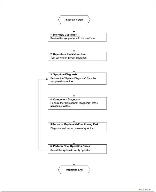
OVERALL SEQUENCE
DETAILED FLOW
1. OBTAIN INFORMATION ABOUT SYMPTOM
Interview the customer to obtain as much information as possible about the conditions and environment under which the malfunction occurred.
>> GO TO 2
2. REPRODUCE THE MALFUNCTION INFORMATION
Check the malfunction on the vehicle that the customer describes.
Inspect the relation of the symptoms and the condition when the symptoms occur.
>> GO TO 3
3. IDENTIFY THE MALFUNCTIONING SYSTEM WITH "SYMPTOM DIAGNOSIS"
Use "Symptom diagnosis" from the symptom inspection result in step 2 and then identify where to start performing the diagnosis based on possible causes and symptoms.
>> GO TO 4
4. PERFORM THE COMPONENT DIAGNOSIS OF THE APPLICABLE SYSTEM
Perform the diagnosis with "Component diagnosis" of the applicable system.
>> GO TO 5
5. REPAIR OR REPLACE THE MALFUNCTIONING PARTS
Repair or replace the specified malfunctioning parts.
>> GO TO 6
6. FINAL CHECK
Check that malfunctions are not reproduced when obtaining the malfunction information from the customer, referring to the symptom inspection result in step 2.
Are the malfunctions corrected?
YES >> Inspection End.
NO >> GO TO 3
DTC/CIRCUIT DIAGNOSIS
 System
System Diagram System Description BASIC OPERATION Power window system is activated by power window switch when ignition switch turns ON. Power window main switch opens/closes all door ...

Other materials:
Air breather hose
Exploded View
1. Cap 2. Air breather hose 3. 2-way connector
Removal and Installation
REMOVAL
Remove air cleaner case. Refer to EM, "Removal and Installation".
Remove air breather hose from the 2-way connector.
CAUTION:
When removing air breather hose, be sure to hold 2- ...
Intake door cable
INTAKE DOOR CABLE : Removal and Installation
REMOVAL
Remove instrument panel assembly. Refer to IP "Removal and
Installation".
Disconnect intake door cable from A/C control.
Disconnect intake door cable from A/C unit assembly and remove.
INSTALLATION
Installation is in the ...
Categories
- Manuals Home
- Nissan Versa Owners Manual
- Nissan Versa Service Manual
- Video Guides
- Questions & Answers
- External Resources
- Latest Updates
- Most Popular
- Sitemap
- Search the site
- Privacy Policy
- Contact Us

0.0058