Nissan Versa (N17): System
System Diagram
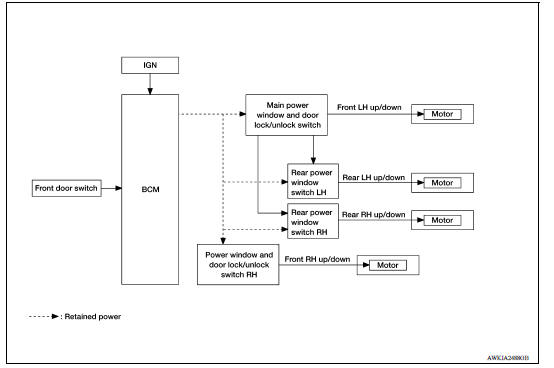
System Description
BASIC OPERATION
- Power window system is activated by power window switch when ignition switch turns ON.
- Power window main switch opens/closes all door glass.
- Front and rear power window switch opens/closes the corresponding door glass.
- AUTO DOWN operation can be performed when power window main switch is depressed to the second detent.
- Power window lock switch can lock all power windows other than driver seat.
POWER WINDOW AUTO-OPERATION (FRONT DRIVER SIDE)
AUTO DOWN operation can be performed when power window main switch is depressed to the second detent.
POWER WINDOW LOCK
Ground circuit inside power window main switch shuts off when power window lock switch is ON. This inhibits each power window switch operation except the power window main switch.
RETAINED POWER OPERATION
- Retained power operation is an additional power supply function that
enables power window system to operate
for an additional 45 seconds after the ignition switch is turned OFF.
RETAINED ACCESSORY POWER CANCEL CONDITIONS:
- Front door CLOSE (door switch OFF)→OPEN (door switch ON).
- When ignition switch is ON again.
- When timer expires. (45 seconds)
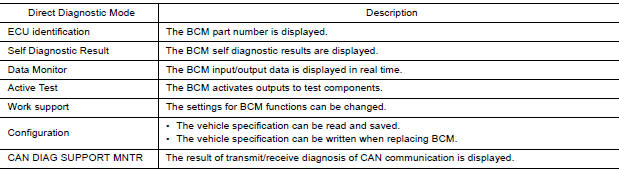
DIAGNOSIS SYSTEM (BCM) (WITH INTELLIGENT KEY SYSTEM)
COMMON ITEM
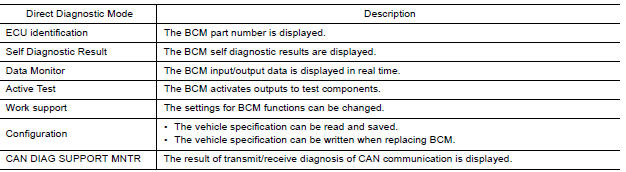
COMMON ITEM : CONSULT Function (BCM - COMMON ITEM)
APPLICATION ITEM
CONSULT performs the following functions via CAN communication with BCM.
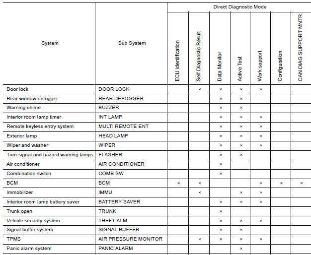
SYSTEM APPLICATION
BCM can perform the following functions.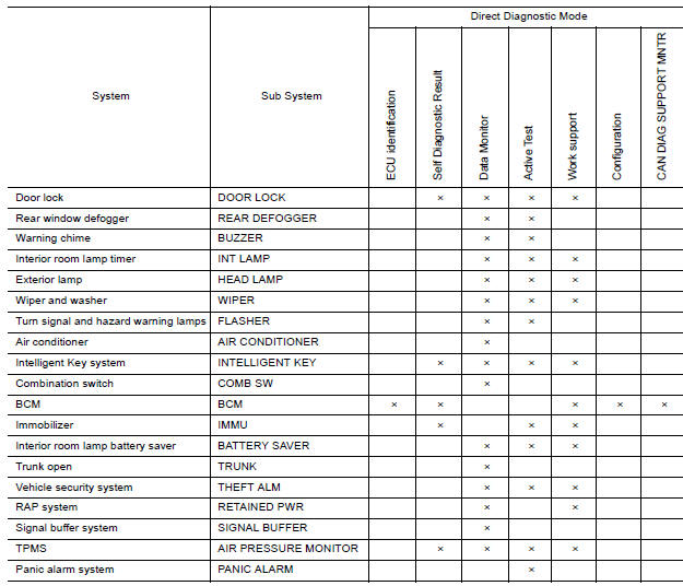
RETAINED PWR
RETAINED PWR : CONSULT Function (BCM - RETAINED PWR)
DATA MONITOR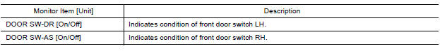
DIAGNOSIS SYSTEM (BCM) (WITHOUT INTELLIGENT KEY SYSTEM)
COMMON ITEM
COMMON ITEM : CONSULT Function (BCM - COMMON ITEM)
APPLICATION ITEM
CONSULT performs the following functions via CAN communication with BCM.
SYSTEM APPLICATION
BCM can perform the following functions.
ECU DIAGNOSIS INFORMATION
BCM
List of ECU Reference
| ECU | Reference |
| BCM (with Intelligent Key system) | BCS "Reference Value" |
| BCS "Fail-safe" | |
| BCS "DTC Inspection Priority Chart" | |
| BCS "DTC Index" | |
| BCM (without Intelligent Key system) | BCS "Reference Value" |
| BCS "Fail-safe" | |
| BCS "DTC Inspection Priority Chart" | |
| BCS "DTC Index" |
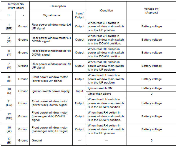
POWER WINDOW MAIN SWITCH
Reference Value
TERMINAL LAYOUT

PHYSICAL VALUES
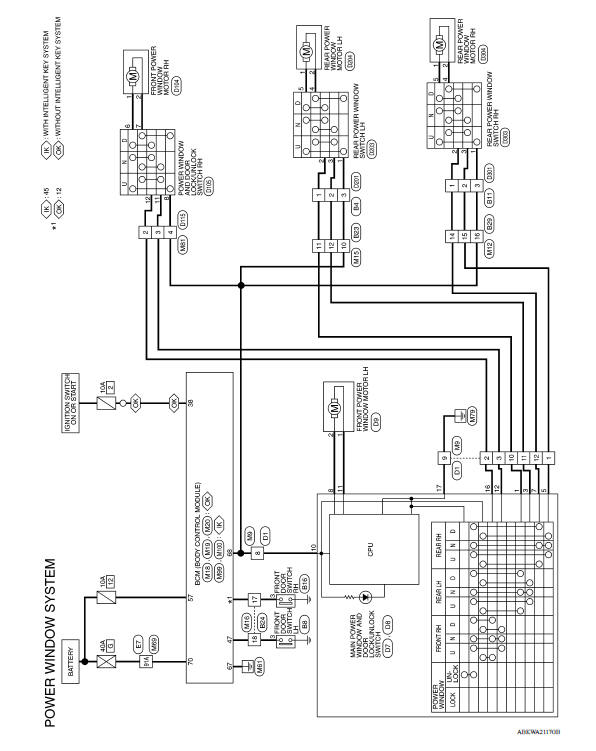
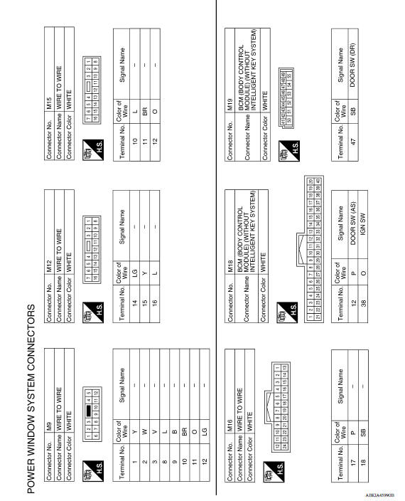
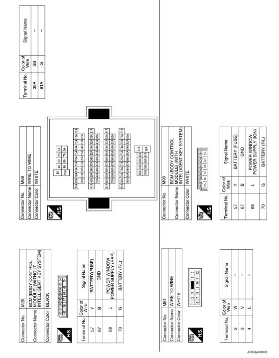
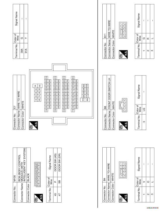
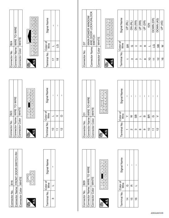
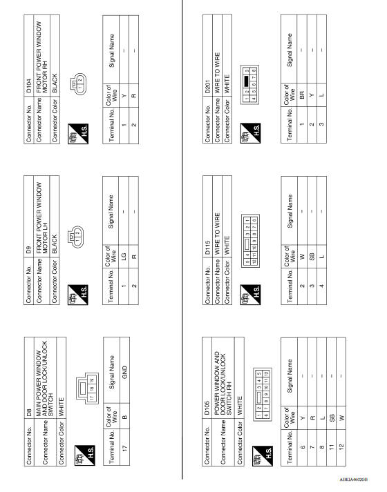
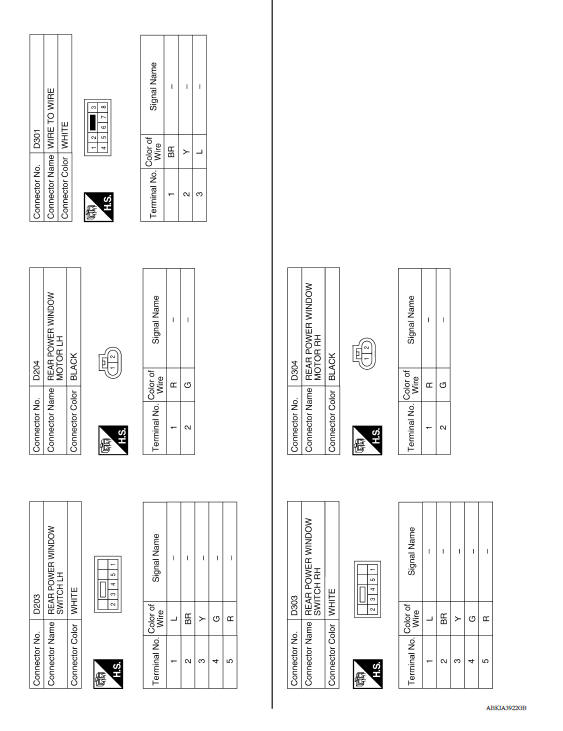
WIRING DIAGRAM
POWER WINDOW SYSTEM
Wiring Diagram
BASIC INSPECTION
 Precautions
Diagnosis and repair work flow
Work Flow OVERALL SEQUENCE DETAILED FLOW 1. OBTAIN INFORMATION ABOUT SYMPTOM Interview the customer to obtain as much information as possible about the conditions and environment under whi ...
Other materials:
Rear drum brake
Exploded View
1. Shoe hold pin 2. Back plate 3. Plug
4. Brake shoe 5. Spring 6. Upper spring
7. Adjuster 8. Return spring 9. Brake drum
10. Boot 11. Piston 12. Piston cup
13. Spring 14. Wheel cylinder 15. Bleeder valve
16. Cap
1: Apply rubber grease.
2: Apply PBC (Poly Butyl Cuprysil) ...
Steering wheel
Exploded View
1. Steering wheel
Removal and Installation
REMOVAL
NOTE:
When reconnecting spiral cable, secure cable with a tape so that case and
rotating part stay aligned. This will
omit neutral position alignment procedure during spiral cable installation.
Set vehicle to the stra ...
Categories
- Manuals Home
- Nissan Versa Owners Manual
- Nissan Versa Service Manual
- Video Guides
- Questions & Answers
- External Resources
- Latest Updates
- Most Popular
- Sitemap
- Search the site
- Privacy Policy
- Contact Us

0.0056