
Nissan Versa (N17): P0713 Transmission fluid temperature sensor A
DTC Logic
DTC DETECTION LOGIC
| DTC | Trouble diagnosis name | DTC detection condition | Possible causes |
| P0713 | Transmission Fluid Temperature Sensor A Circuit High | The CVT fluid temperature identified by the
TCM is −40C (−40F) or less continuously for
5 seconds or more under the following diagnosis
conditions: - Diagnosis conditions - Ignition switch: ON - Vehicle speed: More than 10 km/h (7 MPH) - TCM power supply voltage: More than 11 V |
- Harness or connector
(CVT fluid temperature sensor circuit is
open or shorted to power supply) - CVT fluid temperature sensor |
DTC CONFIRMATION PROCEDURE
1.PREPARATION BEFORE WORK
If another "DTC CONFIRMATION PROCEDURE" occurs just before, turn ignition switch OFF and wait for at least 10 seconds, then perform the next test.
>> GO TO 2.
2.PERFORM DTC CONFIRMATION PROCEDURE
- Start the engine.
- Maintain the following condition for 10 seconds or more.
- Stop the vehicle.
- Check the first trip DTC.
Vehicle speed : 20 km/h (12 MPH) or more
Is "P0713" detected?
YES >> Go to TM "Diagnosis Procedure".
NO >> INSPECTION END
Diagnosis Procedure
1.CHECK CIRCUIT BETWEEN TCM AND CVT UNIT (PART 1)
- Turn ignition switch OFF.
- Disconnect TCM connector and CVT unit connector.
- Check continuity between TCM harness connector terminals and CVT unit
harness connector terminals.
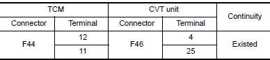
Is the inspection result normal?
YES >> GO TO 2.
NO >> Repair or replace malfunctioning part.
2.CHECK CIRCUIT BETWEEN TCM AND CVT UNIT (PART 2)
- Turn ignition switch ON.
- Check voltage between TCM harness connector terminal and ground.
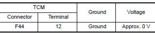
Is the inspection result normal?
YES >> GO TO 3.
NO >> Repair or replace malfunctioning part.
3.CHECK CVT FLUID TEMPERATURE SENSOR
Check CVT fluid temperature sensor. Refer to TM "Component Inspection (CVT Fluid Temperature Sensor)".
Is the inspection result normal?
YES >> Check intermittent incident. Refer to GI "Intermittent Incident".
NO >> Repair or replace malfunctioning parts.
Component Inspection (CVT Fluid Temperature Sensor)
1.CHECK CVT FLUID TEMPERATURE SENSOR
Check resistance between CVT unit connector terminals. 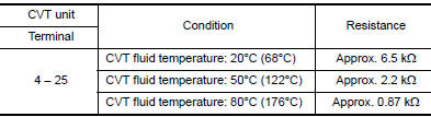
Is the inspection result normal?
YES >> INSPECTION END
NO >> There is a malfunction of CVT fluid temperature sensor. Replace transaxle assembly. Refer to TM "Removal and Installation".
 P0712 Transmission fluid temperature
sensor A
P0712 Transmission fluid temperature
sensor A
DTC Logic DTC DETECTION LOGIC DTC Trouble diagnosis name DTC detection condition Possible causes P0712 Transmission Fluid Temperature Sensor A Circuit Low The CVT ...

Other materials:
Interior lights
The interior light has a three-position switch and
operates regardless of ignition switch position.
When the switch is in the ON position 1 , the
interior lights illuminate, regardless of door position.
The lights will go off after a period of time
unless the ignition switch is placed i ...
Stall test
Work Procedure
INSPECTION
Check the engine oil level. Replenish if necessary.
Check for leak of the CVT fluid. Refer to TM "Inspection".
Drive for about 10 minutes to warm up the vehicle so that the CVT fluid
temperature is 50 to 80C (122 to
176F).
Be sure to apply the par ...
Categories
- Manuals Home
- Nissan Versa Owners Manual
- Nissan Versa Service Manual
- Video Guides
- Questions & Answers
- External Resources
- Latest Updates
- Most Popular
- Sitemap
- Search the site
- Privacy Policy
- Contact Us

0.007