Nissan Versa (N17): P099C Shift solenoid G
DTC Logic
DTC DETECTION LOGIC
| DTC | Trouble diagnosis name | DTC detection condition | Possible causes |
| P099C | Shift solenoid G control circuit high | The TCM high clutch & reverse brake solenoid
valve current monitor reading is 200 mA or
less continuously for 200 msec or more under
the following diagnosis conditions: - Diagnosis conditions - Solenoid valve output current: 750 mA or more - GND short diagnosis of the solenoid valve circuit is not satisfied. - TCM power supply voltage: More than 11 V |
- Harness or connector
(High clutch & reverse brake solenoid
valve circuit is open or shorted to power
supply) - High clutch & reverse brake solenoid valve |
DTC CONFIRMATION PROCEDURE
1.PREPARATION BEFORE WORK
If another "DTC CONFIRMATION PROCEDURE" occurs just before, turn ignition switch OFF and wait for at least 10 seconds, then perform the next test.
>> GO TO 2.
2.CHECK DTC DETECTION
- Start the engine and wait for 5 seconds or more
- Check the first trip DTC.
Is "P099C" detected?
YES >> Go to TM "Diagnosis Procedure".
NO >> INSPECTION END
Diagnosis Procedure
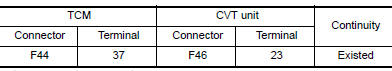
1.CHECK CIRCUIT BETWEEN TCM AND CVT UNIT
- Turn ignition switch OFF.
- Disconnect TCM connector and CVT unit connector.
- Check continuity between TCM harness connector terminal and CVT unit
harness connector terminal.
Is the inspection result normal?
YES >> GO TO 2.
NO >> Repair or replace malfunctioning parts.
2.CHECK HIGH CLUTCH & REVERSE BRAKE SOLENOID VALVE
Check high clutch & reverse brake solenoid valve. Refer to TM "Component Inspection (High Clutch & Reverse Brake Solenoid Valve)".
Is the inspection result normal?
YES >> Check intermittent incident. Refer to GI "Intermittent Incident".
NO >> Repair or replace malfunctioning parts.
Component Inspection (High Clutch & Reverse Brake Solenoid Valve)
1.CHECK HIGH CLUTCH & REVERSE BRAKE SOLENOID VALVE
Check resistance between CVT unit connector terminal and ground. 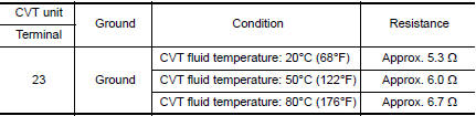
Is the inspection result normal?
YES >> INSPECTION END
NO >> There is a malfunction of high & reverse brake solenoid valve. Replace transaxle assembly.
Refer to TM "Removal and Installation".
 P099B Shift solenoid G
Other materials:
Air conditioning cut control
AIR CONDITIONING CUT CONTROL : System Diagram
AIR CONDITIONING CUT CONTROL : System
Description
INPUT/OUTPUT SIGNAL CHART
Sensor
Input signal to ECM
ECM function
Actuator
Crankshaft position sensor (POS)
Camshaft position sensor (PHASE)
Engine speed*1
Pisto ...
Brake pedal
Inspection and Adjustment
INSPECTION
Brake Pedal Height
Check the height (H1) between the dash lower panel (1) and the
brake pedal upper surface.
(H1) : Refer to BR "Brake Pedal".
CAUTION:
Remove the floor trim.
Stop Lamp Switch
Check the clearance (C) among the brake ped ...
Categories
- Manuals Home
- Nissan Versa Owners Manual
- Nissan Versa Service Manual
- Video Guides
- Questions & Answers
- External Resources
- Latest Updates
- Most Popular
- Sitemap
- Search the site
- Privacy Policy
- Contact Us

0.0057