Nissan Versa (N17): Washer fluid level switch circuit
Description
Transmits the washer fluid level switch signal to the combination meter.
Diagnosis Procedure
Regarding Wiring Diagram information, refer to MWI "Wiring Diagram".
1.CHECK WASHER FLUID LEVEL SWITCH SIGNAL CIRCUIT
1. Turn ignition switch OFF.
2. Disconnect combination meter connector and washer fluid level switch connector.
3. Check continuity between combination meter harness connector M24 terminal
11 and washer fluid level
switch harness connector E50 terminal 1. 
4. Check continuity between combination meter harness connector M24 terminal
11 and ground. 
Is the inspection result normal?
YES >> GO TO 2.
NO >> Repair or replace harness or connector.
2.CHECK WASHER FLUID LEVEL SWITCH GROUND CIRCUIT
Check continuity between washer fluid level switch harness connector E50
terminal 2 and ground. 
Is the inspection result normal?
YES >> Inspection End.
NO >> Repair or replace harness or connector.
Component Inspection
1.CHECK WASHER FLUID LEVEL SWITCH
Check continuity between washer fluid level switch terminals 1 and 2. 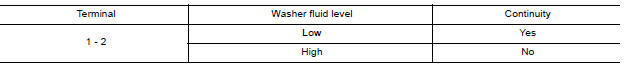
Is the inspection result normal?
YES >> Inspection End.
NO >> Replace washer fluid level switch. Refer to WW "Exploded View".
SYMPTOM DIAGNOSIS
 Fuel level sensor signal circuit
Description The fuel level sensor unit and fuel pump detects the approximate fuel level in the fuel tank and transmits the fuel level signal to the combination meter. ...
The fuel gauge indicator does not
operate
Description Fuel gauge will not indicate from a certain position. Diagnosis Procedure 1.CHECK COMBINATION METER INPUT SIGNAL 1. Select METER/M&A on CONSULT. 2. Using "DATA MONITOR, compare ...
Other materials:
Noise, vibration and harshness (NVH) troubleshooting
NVH troubleshooting Chart
Locate the area where noise occurs.
Confirm the type of noise.
Specify the operating condition of engine.
Check specified noise source
If necessary, repair or replace these parts.
Location
of noise
Type of
noise
Operating condition of
...
P0507 ISC system
Description
The ECM controls the engine idle speed to a specified level through the fine
adjustment of the air, which is let
into the intake manifold, by operating the electric throttle control actuator.
The operating of the throttle valve is
varied to allow for optimum control of the engine ...
Categories
- Manuals Home
- Nissan Versa Owners Manual
- Nissan Versa Service Manual
- Video Guides
- Questions & Answers
- External Resources
- Latest Updates
- Most Popular
- Sitemap
- Search the site
- Privacy Policy
- Contact Us

0.0053