Nissan Versa (N17): P0125 ECT sensor
DTC Logic
DTC DETECTION LOGIC
NOTE:
- If DTC P0125 is displayed with P0116, first perform the trouble diagnosis for DTC P0116. Refer to EC, "DTC Logic".
- If DTC P0125 is displayed with P0117 or P0118, first perform the trouble diagnosis for DTC P0117 or P0118. Refer to EC, "DTC Logic".
| DTC No. | Trouble diagnosis name | DTC detecting condition | Possible cause |
| P0125 | ECT SENSOR (Insufficient engine coolant temperature for closed loop fuel control) |
|
|
DTC CONFIRMATION PROCEDURE
1.PRECONDITIONING
If DTC Confirmation Procedure has been previously conducted, always perform the following procedure before conducting the next test.
- Turn ignition switch OFF and wait at least 10 seconds.
- Turn ignition switch ON.
- Turn ignition switch OFF and wait at least 10 seconds.
>> GO TO 2.
2.CHECK ENGINE COOLANT TEMPERATURE SENSOR FUNCTION
 With CONSULT
- Turn ignition switch ON.
- Select "DATA MONITOR" mode of "ENGINE" using CONSULT.
- Check that "COOLAN TEMP/S" is above 10C (50F).
 With GST
Follow the procedure "With CONSULT" above.
Is it above 5C (41F)?
YES >> INSPECTION END
NO >> GO TO 3.
3.PERFORM DTC CONFIRMATION PROCEDURE
With CONSULT
- Start engine and run it for 65 minutes at idle speed.
- Check 1st tip DTC.
If "COOLAN TEMP/S" indication increases to more than 10C (50F) within 65 minutes, stop engine because the test result will be OK.
CAUTION: Be careful not to overheat engine.
With GST
Follow the procedure "With CONSULT" above.
Is 1st trip DTC detected?
YES >> Proceed to EC, "Diagnosis Procedure".
NO >> INSPECTION END
Diagnosis Procedure
1.CHECK ENGINE COOLANT TEMPERATURE SENSOR
Check the engine coolant temperature sensor. Refer toEC, "Component Inspection".
Is the inspection result normal?
YES >> GO TO 2.
NO >> Replace engine coolant temperature sensor. Refer to CO, "Exploded View".
2.CHECK THERMOSTAT OPERATION
When the engine is cold [lower than 70C (158F)] condition, grasp lower radiator hose and confirm the engine coolant does not flow.
Is the inspection result normal?
YES >> Check intermittent incident. Refer to GI, "Intermittent Incident".
NO >> Repair or replace thermostat. Refer to CO, "Removal and Installation".
Component Inspection
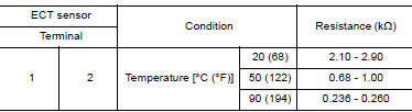
1.CHECK ENGINE COOLANT TEMPERATURE (ECT) SENSOR
- Turn ignition switch OFF.
- Disconnect ECT sensor harness connector.
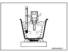
- Remove ECT sensor.
- Check resistance between ECT sensor terminals by heating with hot water as shown in the figure.
Is the inspection result normal?
YES >> INSPECTION END
NO >> Replace engine coolant temperature sensor. Refer to CO, "Exploded View".
 P0122, P0123 TP sensor
Other materials:
Engine control system symptoms
Symptom Table
SYSTEM - BASIC ENGINE CONTROL SYSTEM
1 - 6: The numbers refer to the order of inspection.
(continued on next table)
SYSTEM - ENGINE MECHANICAL & OTHER
1 - 6: The numbers refer to the order of inspection. ...
P0963 Pressure control solenoid A
DTC Logic
DTC DETECTION LOGIC
DTC
Trouble diagnosis name
DTC detection condition
Possible causes
P0963
Pressure Control Solenoid "A"
Control Circuit High
The following diagnosis conditions
are met, and the current
monitor reading of the TCM line
pressure ...
Categories
- Manuals Home
- Nissan Versa Owners Manual
- Nissan Versa Service Manual
- Video Guides
- Questions & Answers
- External Resources
- Latest Updates
- Most Popular
- Sitemap
- Search the site
- Privacy Policy
- Contact Us

0.0059