Nissan Versa (N17): Differential side oil seal
Exploded View
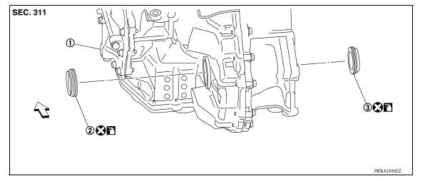
1. Transaxle assembly 2. Differential side oil seal (left side) 3.
Differential side oil seal (right side)
 Front
Front  Genuine
NISSAN Matic S ATF
Genuine
NISSAN Matic S ATF
Removal and Installation
NOTE: When removing components such as hoses, tubes/lines, etc., cap or plug openings to prevent fluid from spilling.
REMOVAL
- Remove the front drive shafts from the transaxle assembly. Refer to FAX "Removal and Installation".
- Remove the differential side oil seal using suitable tool.
CAUTION: When removing the differential side oil seal, be careful not to scratch the oil seal mating surfaces of the transaxle case and converter housing.
INSTALLATION
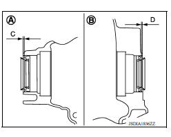
1. Drive the differential side oil seal into the transaxle case side (A) and converter housing side (B) using suitable tool to the specified dimension.
CAUTION:
- Be careful not to scratch the lip of the differential side oil seal when press-fitting it.
- Do not reuse differential side oil seal.
- Apply Genuine NISSAN Matic S ATF to the differential side oil seal lip and around the oil seal.
Dimension (C) : 1.8 +- 0.5 mm (0.071 +- 0.020 in).
Dimension (D) : 1.8 +- 0.5 mm (0.071 +- 0.020 in).
2. Install the front drive shaft. Refer to FAX "Removal and Installation".
Inspection and Adjustment
INSPECTION AFTER INSTALLATION
Check for A/T fluid leakage. Refer to TM "Inspection".
ADJUSTMENT AFTER INSTALLATION
Check the A/T fluid level. Refer to TM "Adjustment".
 Output speed sensor
Exploded View 1. Output speed sensor 2. O-ring 3. Transaxle assembly Front Removal and Installation REMOVAL Remove the front LH wheel and tire. Disconnect the harness connector from o ...
Fluid cooler tube
Exploded View 1. Fluid cooler tube A 2. Copper sealing washer 3. Fluid cooler tube B 4. Bolt 5. Transaxle assembly Removal and Installation WARNING: Do not open the radiator cap or drain p ...
Other materials:
Before starting the engine
Make sure the area around the vehicle is
clear.
Check fluid levels such as engine oil, coolant,
brake and clutch fluid (if so equipped),
and windshield-washer fluid as frequently as
possible, or at least whenever you refuel.
Check that all windows and lights are clean.
Visually insp ...
Disc rotor
DISC ROTOR : Inspection and Adjustment
INSPECTION
Appearance
Check surface of disc rotor for uneven wear, cracks, and serious damage.
Replace it if necessary. Refer to
BR "DISC ROTOR : Inspection and Adjustment".
Runout
Fix the disc rotor to the wheel hub and bearing assembly wi ...
Categories
- Manuals Home
- Nissan Versa Owners Manual
- Nissan Versa Service Manual
- Video Guides
- Questions & Answers
- External Resources
- Latest Updates
- Most Popular
- Sitemap
- Search the site
- Privacy Policy
- Contact Us

0.0074