Nissan Versa (N17): DLC Branch line circuit
Diagnosis Procedure
1.CHECK CONNECTOR
1. Turn the ignition switch OFF.
2. Disconnect the battery cable from the negative terminal.
3. Check the terminals and connectors of the data link connector for damage, bend and loose connection (connector side and harness side).
Is the inspection result normal?
YES >> GO TO 2.
NO >> Repair the terminal and connector.
2.CHECK HARNESS FOR OPEN CIRCUIT
Check the resistance between the data link connector terminals.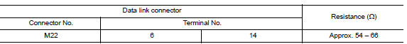
Is the measurement value within the specification?
YES (Present error)>>Check CAN system type decision again.
YES (Past error)>>Error was detected in the data link connector branch line circuit.
NO >> Repair the data link connector branch line.
 A-BAG Branch line circuit
Diagnosis Procedure WARNING: Always observe the following items for preventing accidental activation. Before servicing, turn ignition switch OFF, disconnect battery negative terminal, and wai ...
EPS Branch line circuit 
Diagnosis Procedure 1.CHECK CONNECTOR 1. Turn the ignition switch OFF. 2. Disconnect the battery cable from the negative terminal. 3. Check the terminals and connectors of the EPS control unit f ...
Other materials:
Stall test
Work Procedure
INSPECTION
Check the engine oil level. Replenish if necessary.
Check for leak of the CVT fluid. Refer to TM "Inspection".
Drive for about 10 minutes to warm up the vehicle so that the CVT fluid
temperature is 50 to 80C (122 to
176F).
Be sure to apply the par ...
Front stabilizer
Exploded View
1. Stabilizer bar 2. Stabilizer clamp 3. Stabilizer bushing
4. Stabilizer connecting rod 5. Strut assembly 6. Front suspension member
Front
Removal and Installation
REMOVAL
Remove wheel and tire assemblies using power tool. Refer to WT
"Adjustment".
Remove ...
Categories
- Manuals Home
- Nissan Versa Owners Manual
- Nissan Versa Service Manual
- Video Guides
- Questions & Answers
- External Resources
- Latest Updates
- Most Popular
- Sitemap
- Search the site
- Privacy Policy
- Contact Us

0.0057