Nissan Versa (N17): C1120, C1122, C1124, C1126 ABS In valve system
DTC Logic
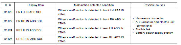
DTC DETECTION LOGIC
DTC CONFIRMATION PROCEDURE
1.CHECK SELF DIAGNOSTIC RESULT
With CONSULT.
- Turn ignition switch ON.
- Perform self diagnostic result.
Is DTC C1120, C1122, C1124 or C1126 detected?
YES >> Proceed to diagnosis procedure. Refer to BRC "Diagnosis Procedure".
NO >> Inspection End.
Diagnosis Procedure
Regarding Wiring Diagram information, refer to BRC "Wiring Diagram".
1.CONNECTOR INSPECTION
- Turn ignition switch OFF.
- Disconnect ABS actuator and electric unit (control unit) connector.
- Check connector and terminals for deformation, disconnection, looseness or damage.
Is the inspection result normal?
YES >> GO TO 2
NO >> Repair or replace as necessary.
2.CHECK ABS ACTUATOR AND ELECTRIC UNIT (CONTROL UNIT) BATTERY POWER SUPPLY
Check voltage between ABS actuator and electric unit (control unit) connector
E33 terminal 25 and ground. 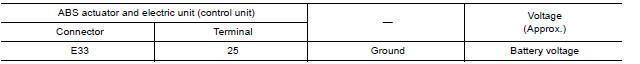
Is the inspection result normal?
YES >> GO TO 3.
NO >> Repair or replace malfunctioning components.
3.CHECK ABS ACTUATOR AND ELECTRIC UNIT (CONTROL UNIT) GROUND CIRCUIT
Check continuity between ABS actuator and electric unit (control unit)
connector E33 terminals 13, 38 and
ground. 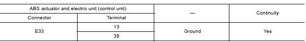
Is the inspection result normal?
YES >> Replace ABS actuator and electric unit (control unit). Refer to BRC "Removal and Installation".
NO >> Repair or replace malfunctioning components.
 C1116 Stop lamp switch
Other materials:
P2760 Torque converter
Description
This DTC is detected when the torque converter clutch solenoid valve is
electrically normal but the torque converter
clutch does not engage. This is not due to an electrical malfunction (circuit
open or shorted), but is
instead due to a mechanical malfunction (sticking of the con ...
A/C Unit assembly
Exploded View
1. Cap 2. Steering member 3. Cap
4. Bracket 5. A/C unit assembly Pawl
Removal and Installation
CAUTION: Perform oil return operation before each refrigeration system
disassembly. However, if a large
amount of refrigerant or oil is detected, do not perform oil return operati ...
Categories
- Manuals Home
- Nissan Versa Owners Manual
- Nissan Versa Service Manual
- Video Guides
- Questions & Answers
- External Resources
- Latest Updates
- Most Popular
- Sitemap
- Search the site
- Privacy Policy
- Contact Us

0.0062