Nissan Versa (N17): B2627 Outside antenna
DTC Logic
DTC DETECTION LOGIC 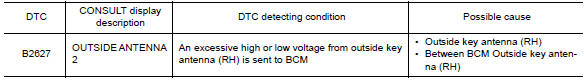
DTC CONFIRMATION PROCEDURE
1.PERFORM DTC CONFIRMATION PROCEDURE
- Turn ignition switch ON.
- Check Self Diagnostic Result mode of BCM using CONSULT.
Is outside key antenna DTC detected?
YES >> Refer to DLK "Diagnosis Procedure".
NO >> Outside key antenna (RH) is OK.
Diagnosis Procedure
Regarding Wiring Diagram information, refer to DLK"INTELLIGENT KEY SYSTEM : Wiring Diagram".
1.CHECK OUTSIDE KEY ANTENNA INPUT SIGNAL 1
- Turn ignition switch ON.
- Check signal between BCM harness connector and ground using
oscilloscope.
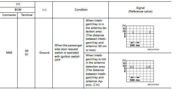
Is the inspection result normal?
YES >> Replace BCM. Refer to BCS "Removal and Installation".
NO >> GO TO 2.
2.CHECK OUTSIDE KEY ANTENNA CIRCUIT
- Turn ignition switch OFF.
- Disconnect BCM connector and outside key antenna (RH) connector.
- Check continuity between BCM harness connector and outside key antenna (RH)
harness connector.

- Check continuity between BCM harness connector and ground.
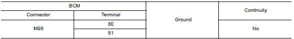
Is the inspection result normal?
YES >> GO TO 3.
NO >> Repair or replace harness.
3.CHECK OUTSIDE KEY ANTENNA INPUT SIGNAL 2
- Replace outside key antenna (RH). (New antenna or other antenna)
- Connect BCM connector and outside key antenna (RH) connector.
- Turn ignition switch ON.
- Check signal between BCM harness connector and ground using
oscilloscope.
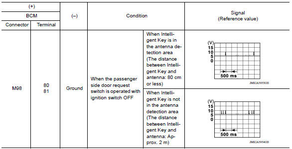
Is the inspection result normal?
YES >> Replace outside key antenna (RH).
NO >> Replace BCM. Refer to BCS "Removal and Installation".
 B2626 Outside antenna
Other materials:
Passenger side
PASSENGER SIDE : Exploded View
WITH REMOVABLE HEADREST
1. Seatback trim 2. Seatback pad 3. Headrest
4. Headrest holder (free) 5. Headrest holder (locked) 6. Chute rod
7. Seat frame assembly 8. Side air bag module 9. Recline lever 10. Seat cushion
outer finisher (RH) 11. Seat cushion trim 1 ...
L Terminal circuit (open)
Description
The "L" terminal circuit controls the charge warning lamp. The charge warning
lamp turns ON when the ignition
switch is set to ON or START. When the generator is providing sufficient voltage
with the engine running,
the charge warning lamp turns OFF. If the charge warning lamp i ...
Categories
- Manuals Home
- Nissan Versa Owners Manual
- Nissan Versa Service Manual
- Video Guides
- Questions & Answers
- External Resources
- Latest Updates
- Most Popular
- Sitemap
- Search the site
- Privacy Policy
- Contact Us

0.0068