Nissan Versa (N17): P0130 A/F sensor 1
DTC Logic
DTC DETECTION LOGIC
To judge malfunctions, the diagnosis checks that the A/F signal computed by ECM from the A/F sensor 1 signal fluctuates according to fuel feedback control.
| DTC No. | Trouble diagnosis name | DTC detecting condition | Possible cause |
| P0130 | Air fuel ratio (A/F) sensor 1 circuit | The A/F signal computed by ECM from the A/F sensor 1 signal is constantly approx. 2.2 V. |
|
DTC CONFIRMATION PROCEDURE
1.PRECONDITIONING
If DTC Confirmation Procedure has been previously conducted, always perform the following procedure before conducting the next test.
- Turn ignition switch OFF and wait at least 10 seconds.
- Turn ignition switch ON.
- Turn ignition switch OFF and wait at least 10 seconds.
TESTING CONDITION: Before performing the following procedure, confirm that battery voltage is more than 11 V at idle.
Do you have CONSULT?
YES >> GO TO 2.
NO >> GO TO 6.
2.CHECK AIR FUEL RATIO (A/F) SENSOR 1 FUNCTION
- Start engine and warm it up to normal operating temperature.
- Select "ENGINE" using CONSULT.
- Select "A/F SEN1 (B1)" in "DATA MONITOR" mode.
- Check "A/F SEN1 (B1)" indication.
Does the indication fluctuate around 2.2 V?
YES >> GO TO 3.
NO >> Go to EC, "Diagnosis Procedure".
3.PERFORM DTC CONFIRMATION PROCEDURE FOR MALFUNCTION I
- Select "ENGINE" using CONSULT.
- Select "A/F SEN1 (B1) P1276" (for DTC P0130) of "A/F SEN1" in "DTC WORK SUPPORT" mode.
- Touch "START".
- When the following conditions are met, "TESTING" will be displayed on the CONSULT screen.
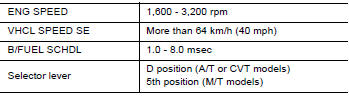
If "TESTING" is not displayed after 20 seconds, retry from step 2.
CAUTION: Always drive vehicle at a safe speed.
Is "TESTING" displayed on CONSULT screen?
YES >> GO TO 4.
NO >> Check A/F sensor 1 function again. GO TO 2.
4.PERFORM DTC CONFIRMATION PROCEDURE FOR MALFUNCTION II
Release accelerator pedal fully.
NOTE: Never apply brake when releasing the accelerator pedal.
Which does "TESTING" change to?
COMPLETED>>GO TO 5.
OUT OF CONDITION>>Retry DTC CONFIRMATION PROCEDURE. GO TO 3.
5.PERFORM DTC CONFIRMATION PROCEDURE FOR MALFUNCTION III
Touch "SELFDIAG RESULT".
Which is displayed on CONSULT screen?
OK >> INSPECTION END
NG >> Go to EC, "Diagnosis Procedure".
6.PERFORM COMPONENT FUNCTION CHECK FOR MALFUNCTION
Perform component function check. Refer to EC, "Component Function Check".
NOTE: Use component function check to check the overall function of the A/F sensor 1 circuit. During this check, a 1st trip DTC might not be confirmed.
Is the inspection result normal?
YES >> INSPECTION END
NO >> Go to EC, "Diagnosis Procedure".
Component Function Check
1.PERFORM COMPONENT FUNCTION CHECK
 With GST
- Start engine and warm it up to normal operating temperature.
- Drive the vehicle at a speed of 80 km/h (50 MPH) for a few minutes in the suitable gear position.
- Shift the selector lever to D position (A/T or CVT) or 5th position
(M/T), then release the accelerator pedal
fully until the vehicle speed decreases to 50 km/h (30 MPH).
CAUTION: Always drive vehicle at a safe speed.
NOTE: Never apply brake when releasing the accelerator pedal.
- Repeat steps 2 and 3 for five times.
- Stop the vehicle and turn ignition switch OFF.
- Turn ignition switch ON.
- Turn ignition switch OFF and wait at least 10 seconds.
- Restart engine.
- Repeat steps 2 and 3 for five times.
- Stop the vehicle and connect GST to the vehicle.
- Check 1st trip DTC.
Is 1st trip DTC detected?
YES >> Go to EC, "Diagnosis Procedure".
NO >> INSPECTION END
Diagnosis Procedure
1.CHECK GROUND CONNECTION
- Turn ignition switch OFF.
- Check ground connection E. Refer to Ground Inspection in GI, "Circuit Inspection".
Is the inspection result normal?
YES >> GO TO 2.
NO >> Repair or replace ground connection.
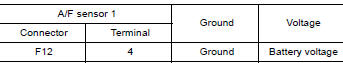
2.CHECK AIR FUEL RATIO (A/F) SENSOR 1 POWER SUPPLY CIRCUIT
- Disconnect A/F sensor 1 harness connector.
- Turn ignition switch ON.
- Check the voltage between A/F sensor 1 harness connector and ground.
Is the inspection result normal?
YES >> GO TO 4.
NO >> GO TO 3.
3.DETECT MALFUNCTIONING PART
Check the following.
- IPDM E/R harness connector F42
- 20A fuse (No. 53)
- Harness for open or short between A/F sensor 1 and fuse
>> Repair or replace harness or connectors.
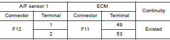
4.CHECK A/F SENSOR 1 INPUT SIGNAL CIRCUIT FOR OPEN AND SHORT
- Turn ignition switch OFF.
- Disconnect ECM harness connector.
- Check the continuity between A/F sensor 1 harness connector and ECM harness connector.
4. Check the continuity between A/F sensor 1 harness connector and ground or ECM harness connector and ground.
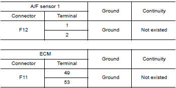
5. Also check harness for short to power.
Is the inspection result normal?
YES >> GO TO 5.
NO >> Repair open circuit, short to ground or short to power in harness or connectors.
5.CHECK INTERMITTENT INCIDENT
Perform GI, "Intermittent Incident".
Is the inspection result normal?
YES >> GO TO 6.
NO >> Repair or replace.
6.REPLACE AIR FUEL RATIO (A/F) SENSOR 1
Replace malfunctioning air fuel ratio (A/F) sensor 1. Refer to EM, "Exploded View".
CAUTION:
- Discard any A/F sensor which has been dropped from a height of more than 0.5 m (19.7 in) onto a hard surface such as a concrete floor; use a new one.
- Before installing new A/F sensor, clean exhaust system threads using Oxygen Sensor Thread Cleaner [commercial service tool (J4389718 or J4389712)] and approved antiseize lubricant (commercial service tool).
>> INSPECTION END
 P0128 thermostat function
Other materials:
U0073 Communication bus A off
Description
CAN (Controller Area Network) is a serial communication line for real-time
application. It is an on-vehicle multiplex
communication line with high data communication speed and excellent malfunction
detection ability.
Many electronic control units are equipped onto a vehicle, an ...
Rear seat
Exploded View - Fixed Seatback
FIXED SEATBACK
1. Headrest holder (locked) 2. Headrest holder (free) 3. Rear seatback
assembly
4. Seatback trim 5. Seatback pad 6. LATCH bracket (RH)
7. Seat cushion assembly 8. Seat cushion trim 9. Seat cushion pad
10. Seat cushion hook 11. LATCH bracket (L ...
Categories
- Manuals Home
- Nissan Versa Owners Manual
- Nissan Versa Service Manual
- Video Guides
- Questions & Answers
- External Resources
- Latest Updates
- Most Popular
- Sitemap
- Search the site
- Privacy Policy
- Contact Us

0.0057