Nissan Versa (N17): P2100, P2103 throttle control motor relay
DTC Logic
DTC DETECTION LOGIC
| DTC No. | Trouble diagnosis name | DTC detecting condition | Possible cause |
| P2100 | Throttle control motor relay circuit open | ECM detects a voltage of power source for throttle control motor is excessively low. |
|
| P2103 | Throttle control motor relay circuit short | ECM detect the throttle control motor relay is stuck ON. |
|
DTC CONFIRMATION PROCEDURE
1.PRECONDITIONING
If DTC Confirmation Procedure has been previously conducted, always perform the following before conducting the next test.
- Turn ignition switch OFF and wait at least 10 seconds.
- Turn ignition switch ON.
- Turn ignition switch OFF and wait at least 10 seconds.
TESTING CONDITION: Before performing the following procedure, confirm that battery voltage is more than 8 V.
Witch DTC is detected?
P2100 >> GO TO 2.
P2103 >> GO TO 3.
2.PERFORM DTC CONFIRMATION PROCEDURE FOR DTC P2100
- Turn ignition switch ON and wait at least 2 seconds.
- Start engine and let it idle for 5 seconds.
- Check DTC.
Is DTC detected?
YES >> Go to EC, "Diagnosis Procedure".
NO >> INSPECTION END
3.PERFORM DTC CONFIRMATION PROCEDURE FOR DTC P2103
- Turn ignition switch ON and wait at least 1 second.
- Check DTC.
Is DTC detected?
YES >> Go to EC, "Diagnosis Procedure".
NO >> INSPECTION END
Diagnosis Procedure
1.CHECK THROTTLE CONTROL MOTOR RELAY POWER SUPPLY CIRCUIT-I
- Turn ignition switch OFF.
- Check voltage between ECM harness connector and ground
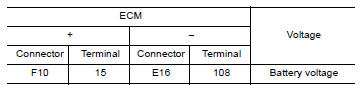
Is the inspection result normal?
YES >> GO TO 5.
NO >> GO TO 2.
2.CHECK THROTTLE CONTROL MOTOR RELAY INPUT SIGNAL CIRCUIT-I
- Disconnect ECM harness connector.
- Disconnect IPDM E/R harness connector F115.
- Check the continuity between ECM harness connector and IPDM E/R harness
connector.
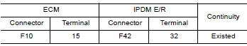
- Also check harness for short to ground and short to power.
Is the inspection result normal?
YES >> GO TO 4.
NO >> GO TO 3.
3.DETECT MALFUNCTIONING PART
Check the following.
- IPDM E/R connector F42
- Harness for open or short between IPDM E/R and ECM
>> Repair open circuit or short to ground or short to power in harness or connectors.
4.CHECK FUSE
- Disconnect 20 A fuse (No. 53) from IPDM E/R.
- Check 20 A fuse for blown.
Is the inspection result normal?
YES >> GO TO 9.
NO >> Replace 20 A fuse.
5.CHECK THROTTLE CONTROL MOTOR RELAY INPUT SIGNAL CIRCUIT-I
- Check voltage between ECM harness connector and ground under the
following conditions.
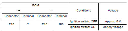
Is the inspection result normal?
YES >> GO TO 8.
NO >> GO TO 6.
6.CHECK THROTTLE CONTROL MOTOR RELAY INPUT SIGNAL CIRCUIT-II
- Turn ignition switch OFF.
- Disconnect ECM harness connector.
- Disconnect IPDM E/R harness connector F42.
- Check the continuity between ECM harness connector and IPDM E/R harness
connector.
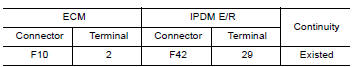
- Also check harness for short to ground and short to power.
Is the inspection result normal?
YES >> GO TO 8.
NO >> GO TO 7.
7.DETECT MALFUNCTIONING PART
Check the following.
- IPDM E/R connector F42
- Harness for open or short between IPDM E/R and ECM
>> Repair open circuit or short to ground or short to power in harness or connectors.
8.CHECK FUSE
- Disconnect 15 A fuse (No. 52) from IPDM E/R.
- Check 15 A fuse for blown.
Is the inspection result normal?
YES >> GO TO 9.
NO >> Replace 15 A fuse.
9.CHECK INTERMITTENT INCIDENT
Refer to GI, "Intermittent Incident".
Is the inspection result normal?
YES >> Replace IPDM E/R. Refer to PCS, "Removal and Installation" (WITH I-KEY) or PCS, "Removal and Installation" (WITHOUT I-KEY).
NO >> Repair or replace harness or connectors.
 P2096, P2097 A/F sensor 1
Other materials:
U0073 Communication bus A off
Description
CAN (Controller Area Network) is a serial communication line for real-time
application. It is an on-vehicle multiplex
communication line with high data communication speed and excellent malfunction
detection ability.
Many electronic control units are equipped onto a vehicle, an ...
Rear pillar finisher
REAR PILLAR FINISHER : Removal and Installation
REMOVAL
Partially remove rear body side welt. Refer to INT "BODY SIDE WELT :
Removal and Installation".
Remove rear seat cushion. Refer to SE "Removal and Installation - Seat
Cushion Assembly".
Remove the rear seat bo ...
Categories
- Manuals Home
- Nissan Versa Owners Manual
- Nissan Versa Service Manual
- Video Guides
- Questions & Answers
- External Resources
- Latest Updates
- Most Popular
- Sitemap
- Search the site
- Privacy Policy
- Contact Us

0.0135