Nissan Versa (N17): Engine assembly
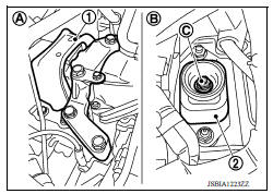
Exploded View
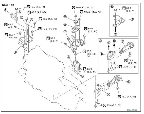
1. Engine mounting (RH) stay 2. Engine mount (RH) stay 3. Engine mounting insulator (RH) 4. Rear engine mounting bracket 5. Rear torque rod 6. Engine mounting bracket (LH) 7. Engine mounting bracket (LH) 8. Engine mounting insulator (LH) 9. Mass damper A. Front mark B. Transaxle (upper) C. Transaxle (lower) D. M/T models
CAUTION:
Check that the stud bolt (*2) is tight at the specified torque before tightening the nut (*1) shown. [Stud bolt (*2) may be loosened after loosening the nut (*1)]
Removal and Installation
WARNING:
- Position the vehicle on a flat and solid surface.
- Place chocks at front and back of rear wheels.
- Attach proper slingers and bolts described in PARTS CATALOG if engine is not already equipped.
CAUTION:
- Always be careful to work safely.
- Do not start working until exhaust system and coolant are cool enough.
- If items or work required are not covered by the engine section, refer to the applicable sections.
- Always use the support point specified for lifting.
- Use either 2pole lift type or separate type lift. If boardon type must be used, support the rear axle jacking point with a transmission jack or similar tool before starting work, in preparation for the backward shift of center of gravity.
- For supporting points for lifting and jacking point at rear axle.
NOTE:
- When removing components such as hoses, tubes/lines, etc., cap or plug openings to prevent fluid from spilling.
- Remove the engine and the transaxle assembly from the vehicle downward. Separate the engine and the transaxle.
REMOVAL
Preparation
- Release fuel pressure.
- Drain engine coolant from radiator.
CAUTION:
- Perform this step when the engine is cold.
- Do not spill engine coolant on drive belts.
3. Remove the following parts:
- Front road wheels and tires (RH/LH).
- Front fender protector (RH/LH).
- Drive belt:
- Battery and battery tray.
- Air duct (inlet), air duct, and air cleaner case assembly.
- Radiator hose (upper and lower).
- Exhaust front tube.
Engine Room (LH)
1. Disconnect all connections of engine harness around the battery, and then temporarily secure the engine harness into the engine side.
CAUTION:
Protect connectors against foreign materials during the operation by wrapping in a plastic bag.
- Disconnect heater hoses.
- Disconnect fuel feed hose at engine side.
- Disconnect control linkage cable from transaxle.
- Disconnect clutch tube on transaxle side from clutch damper.
Engine Room (RH)
- Remove alternator.
- Disconnect vacuum hose at engine side.
- Remove EVAP hoses at engine side.
- Remove air conditioner compressor from the engine with the piping connected. Temporarily position the air conditioner compressor on the vehicle side with a rope without placing a heavy load on the piping.
Vehicle Underbody
- Remove ground cable at transaxle side.
- Remove drive shafts (RH/LH).
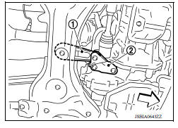
- Remove rear torque rod (1).
(2) : Rear engine mounting bracket
 : Front
4. Preparation for the work of transaxle is as follows:
- Remove transaxle joint bolts which pierce at oil pan (upper) lower rear side.
Removal
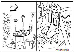
1. When engine can be hoisted, install engine slinger to cylinder head front left side (A) and rear right side (B) and support the engine position with a suitable tool.
 : Engine front
Slinger (A) bolts : 65.0 N*m (6.6 kgm, 48 ftlb)
Slinger (B) bolts : 25.0 N*m (2.6 kgm, 18 ftlb)
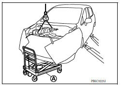
2. Use a suitable tool (A) to securely support the bottom of the engine and the transaxle assembly
CAUTION:
Put a piece of wood or an equivalent as the supporting surface and secure in a stable condition.
3. Remove engine mounting insulator (RH) (1).
(2) : Engine mounting insulator (LH)
(A) : Engine front side
(B) : Transaxle side
4. Remove engine through boltsecuring nut (C).
5. Carefully lower jack, or raise lift to remove the engine and the transaxle assembly. Observe the following cautions:
CAUTION:
- Check that no part interferes with the vehicle side.
- Before and during lifting, always check if any harnesses are left connected.
- During removal, always be careful to prevent the vehicle from falling off the lift due to changes in the center of gravity.
- If necessary, support the vehicle by setting jack or suitable tool at the rear.
Separation
- Remove starter motor.
- Lift with a hoist and separate the engine from the transaxle assembly.
INSTALLATION
Installation is in the reverse order of removal.
CAUTION:
- Do not allow engine oil to get on engine mounting insulator. Be careful not to damage engine mounting insulator.
- Check that each mounting insulator is seated properly, and tighten nuts and bolts.
- When installation directions are specified, install parts according to the direction marks on them, referring to the figure of components.
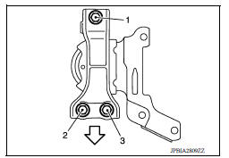
Engine Mounting Insulator (RH)
- Tighten bolts in the numerical order as shown.
: Front
INSPECTION AFTER INSTALLATION
- Before starting engine, check oil/fluid levels including engine coolant and engine oil. If less than required quantity, fill to the specified level.
- Use procedure below to check for fuel leakage.
- Turn ignition switch ON (with engine stopped). With fuel pressure applied to fuel piping, check for fuel leakage at connection points.
- Start engine. With engine speed increased, check again for fuel leakage at connection points.
- Run engine to check for unusual noise and vibration.
NOTE:
If hydraulic pressure inside timing chain tensioner drops after removal and installation, slack in the guide may generate a pounding noise during and just after engine start. However, this is normal. Noise will stop after hydraulic pressure rises.
- Warm up engine thoroughly to make sure there is no leakage of fuel, exhaust gas, or any oils/fluids including engine oil and engine coolant.
- Bleed air from passages in lines and hoses, such as in cooling system.
- After cooling down engine, again check oil/fluid levels including engine oil and engine coolant. Refill to specified level, if necessary.
- Summary of the inspection items:
| Item | Before starting engine | Engine running | After engine stopped | |
| Engine coolant | Level | Leakage | Level | |
| Engine oil | Level | Leakage | Level | |
| Transmission/ transaxle fluid | A/T and CVT Models | Leakage | Level/Leakage | Leakage |
| M/T Models | Level/Leakage | Leakage | Level/Leakage | |
| Other oils and fluids* | Level | Leakage | Level | |
| Fuel | Leakage | Leakage | Leakage | |
| Exhaust gas | Leakage | |||
*Power steering fluid, brake fluid, etc.
 Cylinder head
Engine stand setting
Setting NOTE: The following procedures explain how to disassemble the engine with the engine stand fastened to the bell housing. Some steps may be different if using a different type of engine ...
Other materials:
Vehicle Dynamic Control (VDC) off switch
The vehicle should be driven with the VDC system
on for most driving conditions.
If the vehicle is stuck in mud or snow, the VDC
system reduces the engine output to reduce
wheel spin. The engine speed will be reduced
even if the accelerator is depressed to the floor. If
maximum engine po ...
Oil pan (lower)
Exploded View
1. Rear oil seal 2. Oring 3. Oil pan (upper) 4. Oil pump chain tensioner
(for oil pump drive chain) 5. Oil pump drive chain 6. Crankshaft key 7.
Crankshaft sprocket 8. Oil pump sprocket 9. Oil pump 10. Oring 11. Oring 12.
Oil pan drain plug 13. Drain plug washer 14. Oil pan ...
Categories
- Manuals Home
- Nissan Versa Owners Manual
- Nissan Versa Service Manual
- Video Guides
- Questions & Answers
- External Resources
- Latest Updates
- Most Popular
- Sitemap
- Search the site
- Privacy Policy
- Contact Us

0.0062