Nissan Versa (N17): Engine stand setting
Setting
NOTE: The following procedures explain how to disassemble the engine with the engine stand fastened to the bell housing. Some steps may be different if using a different type of engine stand.
1. Install engine to engine stand:
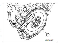
a. Remove flywheel or drive plate.
- Secure flywheel (1) (M/T models) or drive plate (A/T or CVT models) using Tool (A), and remove bolts.
Tool number : KV11105210 (J44716)
CAUTION:
- Do not disassemble flywheel.
- Do not place flywheel or drive plate with signal plate facing down.
- When handling signal plate, take care not to damage or scratch it.
- Handle signal plate in a manner that prevents it from becoming magnetized.
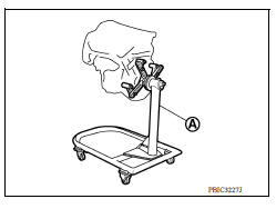
b. Lift the engine with a hoist to install it onto a suitable tool.
CAUTION:
- Use the engine stand that has a load capacity approximately 150 kg (331 lb) or more large enough for supporting the engine weight.
- If the load capacity of stand is not adequate, remove the
following parts beforehand to reduce the potential risk of overturning
stand.
- Intake manifold.
- Exhaust manifold.
- Rocker cover.
NOTE:
The figure shows an example of widely used engine stand (A) that can support the mating surface of transaxle with flywheel removed.
CAUTION:
Before removing the hanging chains, check the engine stand is stable and there is no risk of overturning.
2. Drain engine oil.
CAUTION:
- Be sure to clean drain plug and install with new drain plug washer.
- Do not reuse drain plug washer.
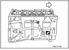
3. Drain engine coolant by removing water drain plug (1) from inside of the engine.
 : Engine front
Use Genuine Silicone RTV Sealant or equivalent.
ENGINE UNIT
Disassembly .
- Remove intake manifold.
- Remove exhaust manifold.
- Remove oil pan (lower).
- Remove ignition coil, spark plug, and rocker cover.
- Remove fuel injector and fuel tube.
- Remove front cover and timing chain.
- Remove camshaft.
- Remove cylinder head.
Assembly
Assembly is in the reverse order of disassembly.
 Engine assembly
Exploded View 1. Engine mounting (RH) stay 2. Engine mount (RH) stay 3. Engine mounting insulator (RH) 4. Rear engine mounting bracket 5. Rear torque rod 6. Engine mounting bracket (LH) 7. ...
Oil pan (upper) and oil strainer
Exploded View 1. Rear oil seal 2. Oring 3. Oil pan (upper) 4. Oil pump chain tensioner (for oil pump drive chain) 5. Oil pump drive chain 6. Crankshaft key 7. Crankshaft sprocket 8. Oil pump ...
Other materials:
Child safety
WARNING
Do not allow children to play with the seat
belts. Most seating positions are
equipped with Automatic Locking Retractor
(ALR) mode seat belts. If the seat belt
becomes wrapped around a child's neck
with the ALR mode activated, the child can
be seriously injured or killed if the seat
...
Side oil seal
Removal and Installation
REMOVAL
Remove front drive shaft from transaxle assembly. Refer to FAX, "Removal
and Installation".
Remove differential side oil seal (1) using suitable tool.
CAUTION:
Do not damage transaxle case and clutch housing.
INSTALLATION
& ...
Categories
- Manuals Home
- Nissan Versa Owners Manual
- Nissan Versa Service Manual
- Video Guides
- Questions & Answers
- External Resources
- Latest Updates
- Most Popular
- Sitemap
- Search the site
- Privacy Policy
- Contact Us

0.0054