Nissan Versa (N17): Front door speaker
Diagnosis Procedure
Regarding Wiring Diagram information, refer to AV "Wiring Diagram".
1.CONNECTOR CHECK
Check the AV control unit and speaker connectors for the following:
- Proper connection
- Damage
- Disconnected or loose terminals
Is the inspection result normal?
YES >> GO TO 2
NO >> Repair the terminals or connectors.
2.CHECK FRONT DOOR SPEAKER SIGNAL CIRCUIT CONTINUITY
1. Disconnect AV control unit connector M70 and suspect front door speaker connector.
2. Check continuity between AV control unit connector M70 and suspect front
door speaker connector.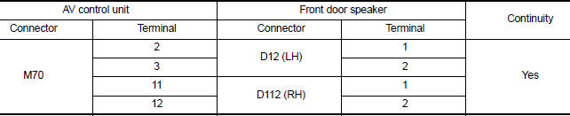
3. Check continuity between AV control unit connector M70 and ground.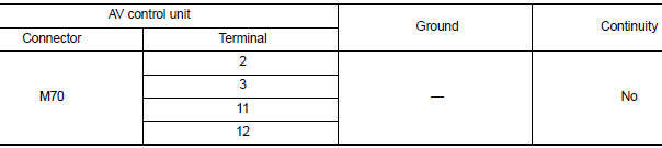
Is the inspection result normal?
YES >> GO TO 3
NO >> Repair or replace harness or connectors.
3.CHECK FRONT DOOR SPEAKER SIGNAL
1. Connect AV control unit connector M70 and suspect front door speaker connector.
2. Turn ignition switch to ACC.
3. Push AV control unit POWER switch.
4. Check signal between the terminals of AV control unit connector M70.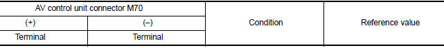
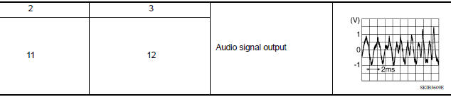
Is the inspection result normal?
YES >> Replace front door speaker. Refer to AV "Removal and Installation".
NO >> Replace AV control unit. Refer to AV "Removal and Installation".
 Power supply and ground circuit
AV CONTROL UNIT AV CONTROL UNIT : Diagnosis Procedure Regarding Wiring Diagram information, refer to AV "Wiring Diagram". 1.CHECK FUSE Check that the following fuses are not blown. Are ...
Rear door speaker
Diagnosis Procedure Regarding Wiring Diagram information, refer to AV "Wiring Diagram". 1.CONNECTOR CHECK Check the AV control unit and speaker connectors for the following: Proper ...
Other materials:
P0507 ISC system
Description
The ECM controls the engine idle speed to a specified level through the fine
adjustment of the air, which is let
into the intake manifold, by operating the electric throttle control actuator.
The operating of the throttle valve is
varied to allow for optimum control of the engine ...
CSC (Concentric slave cylinder)
Exploded View
1. Transaxle assembly 2. CSC (concentric slave cylinder)
Removal and Installation
CAUTION:
Do not reuse CSC (concentric slave cylinder). CSC slides back to
the original position every time
when removing transaxle assembly. At this time, dust on the sliding parts
may ...
Categories
- Manuals Home
- Nissan Versa Owners Manual
- Nissan Versa Service Manual
- Video Guides
- Questions & Answers
- External Resources
- Latest Updates
- Most Popular
- Sitemap
- Search the site
- Privacy Policy
- Contact Us

0.0053