Nissan Versa (N17): Power supply and ground circuit
AV CONTROL UNIT
AV CONTROL UNIT : Diagnosis Procedure
Regarding Wiring Diagram information, refer to AV "Wiring Diagram".
1.CHECK FUSE
Check that the following fuses are not blown.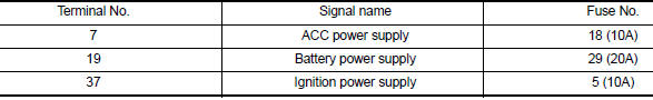
Are the fuses blown?
YES >> Replace the blown fuse after repairing the affected circuit.
NO >> GO TO 2.
2.CHECK POWER SUPPLY CIRCUIT
1. Turn ignition switch OFF.
2. Disconnect AV control unit connectors M70 and M71.
3. Check voltage between AV control unit connectors M70 and M71 and ground.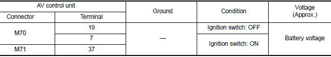
Is the inspection result normal?
YES >> GO TO 3.
NO >> Repair or replace harness or connectors.
3.CHECK GROUND CIRCUIT
1. Turn ignition switch OFF.
2. Check continuity between AV control unit connector M70 and ground.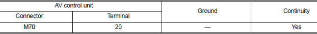
Is the inspection result normal?
YES >> Inspection End.
NO >> Repair or replace harness or connectors.
 U12B1 Power supply voltage
DTC Logic DTC DETECTION LOGIC Diagnosis Procedure 1.CHECK CHARGING SYSTEM Check the vehicle charging system. Refer to CHG "Work Flow (With EXP-800 NI or GR8-1200 NI)" or CHG "W ...
Front door speaker
Diagnosis Procedure Regarding Wiring Diagram information, refer to AV "Wiring Diagram". 1.CONNECTOR CHECK Check the AV control unit and speaker connectors for the following: Proper co ...
Other materials:
P074B Unable to engage 3GR
Description
This malfunction is detected when the A/T does not shift into 3GR position as
instructed by TCM. This is not
only caused by electrical malfunction (circuits open or shorted) but by
mechanical malfunction such as control
valve sticking, improper solenoid valve operation, etc.
DTC ...
Fender protector
Exploded View
1. Fender protector 2. J-nut Front
Removal and Installation
REMOVAL
1. Remove under cover. Refer to EXT"Removal and Installation".
2. Remove fender protector screws and clips.
3. Remove fender protector.
INSTALLATION
Installation is in the reverse order of removal ...
Categories
- Manuals Home
- Nissan Versa Owners Manual
- Nissan Versa Service Manual
- Video Guides
- Questions & Answers
- External Resources
- Latest Updates
- Most Popular
- Sitemap
- Search the site
- Privacy Policy
- Contact Us

0.0081