Nissan Versa (N17): Front suspension member
Exploded View
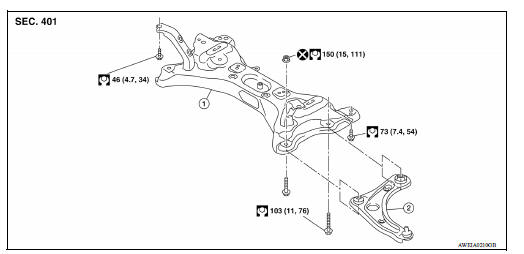
1. Front suspension member 2. Transverse link
Removal and Installation
REMOVAL
- Remove the wheel and tire assemblies using power tool. Refer to WT "Adjustment".
- Remove transverse link. Refer to FSU-12, "Removal and Installation".
- Remove steering outer socket from steering knuckle. Refer to ST "Removal and Installation".
- Separate intermediate shaft from the lower joint. Refer to ST "Removal and Installation".
- Remove the engine rear torque rod.
- Set suitable jack under front suspension member.
CAUTION: Do not damage the front suspension member with jack.
- Remove suspension member bolts.
- Gradually lower the jack to remove front suspension member from vehicle body.
- Remove steering gear assembly from suspension member. Refer to ST "Removal and Installation".
INSTALLATION
Installation is in the reverse order of removal.
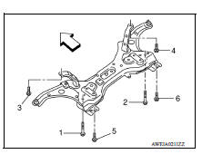
- For installation of the suspension member, temporarily tighten the bolts in the sequence shown and tighten them to the specified torque.
 : Front
- Refer to FSU "Exploded View" for tightening torque.
- Tighten the wheel nuts to specification. Refer to WT "Adjustment".
- After installation, perform final tightening of each part under
unladen conditions with tires on ground. Check wheel alignment.
Refer to FSU "Inspection and Adjustment".
SERVICE DATA AND SPECIFICATIONS (SDS)
Wheel Alignment
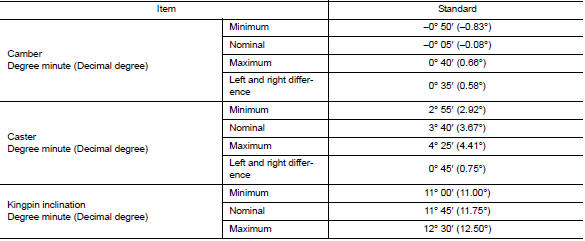
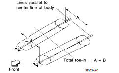
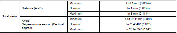
Measure value under unladen* conditions.
*: Fuel, engine coolant and lubricant are full. Spare tire, jack, hand tools and mats are in designated positions.
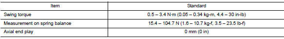
Ball Joint
Wheelarch Height
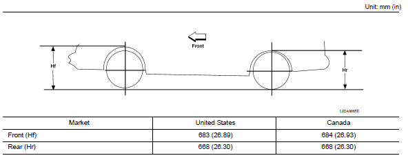
Measure value under unladen* conditions.
*: Fuel, engine coolant and lubricant are full. Spare tire, jack, hand tools and mats are in designated positions.
 Front stabilizer
Exploded View 1. Stabilizer bar 2. Stabilizer clamp 3. Stabilizer bushing 4. Stabilizer connecting rod 5. Strut assembly 6. Front suspension member Front Removal and Installation REMOVAL ...
Precautions
Precaution for Supplemental Restraint System (SRS) "AIR BAG" and "SEAT BELT PRE-TENSIONER" The Supplemental Restraint System such as "AIR BAG" and "SEAT BELT PRE-TENSIONER", us ...
Other materials:
Control panel buttons - color screen with Navigation System (if so equipped)
WARNING
Positioning of the heating or air conditioning
controls and display controls
should not be done while driving in order
that full attention may be given to
the driving operation.
Do not disassemble or modify this system.
If you do, it may result in accidents,
fire, or elec ...
EVAP canister vent control valve
Exploded View
1. EVAP canister 2. O-ring 3. EVAP canister vent control valve
4. EVAP canister vent control valve hose
Removal and Installation
NOTE:
The EVAP canister vent control valve can be removed without removing the EVAP
canister.
REMOVAL
Remove the EVAP canister protector cov ...
Categories
- Manuals Home
- Nissan Versa Owners Manual
- Nissan Versa Service Manual
- Video Guides
- Questions & Answers
- External Resources
- Latest Updates
- Most Popular
- Sitemap
- Search the site
- Privacy Policy
- Contact Us

0.0067