Nissan Versa (N17): Fuel tank
Exploded View
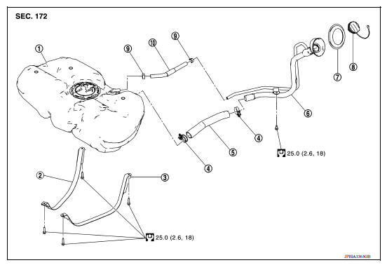
1. Fuel tank 2. Fuel tank mounting band (RH) 3. Fuel tank mounting band (LH) 4. Clamp 5. Fuel filler hose 6. Fuel filler tube 7. Grommet 8. Fuel filler cap 9. Clamp 10. Vent hose
Removal and Installation
WARNING: Be sure to read "General Precautions" before working on the fuel system. Refer to FL, "General Precautions".
REMOVAL
- Release the fuel pressure from the fuel lines. Refer to EC, "Work Procedure".
- Check fuel level with vehicle on a level surface. If the fuel level is 7/8 of the fuel tank (full or nearly full), draw appropriate amount of fuel from the fuel tank.
Guideline : Draw approximately 10 liters (2-5/8 US gal, 2-1/4 imp gal) from a full-tank condition.
- In the event of malfunction in fuel pump, insert a hose measuring 20mm (0.79 in) in diameter into the filler opening to draw approximately 10 liters (2-5/8 US gal, 2-1/4 Imp gal) fuel.
- Open fuel filler lid.
- Open fuel filler cap and release the pressure inside fuel tank.
- Remove the rear seat cushion. Refer to SE, "Removal and Installation - Seat Cushion Assembly".
- Remove the inspection hole cover.
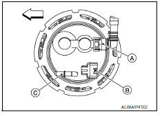
- Disconnect the harness connector (B), fuel feed tube (C) and EVAP tube (A).
 : Front
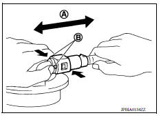
Remove the quick connector as follows:
- Hold the sides of the connector, push in tabs (B) and pull (A) out the tube.
- If the connector and the tube are stuck together, push and pull several times until they start to move. Then disconnect them by pulling.
CAUTION:
- The tube can be removed when the tabs are completely depressed. Do not twist it more than necessary.
- Do not use any tools to remove the quick connector.
- Keep the resin tube away from heat. Be especially careful when welding near the tube.
- Prevent acid liquid such as battery electrolyte, etc. from getting on the resin tube.
- Do not bend or twist the tube during installation and removal.
- Only when the tube is replaced, remove the remaining retainer on the tube or fuel level sensor, fuel filter, and fuel pump assembly.
- When the tube or fuel level sensor, fuel filter, and fuel pump assembly is replaced, also replace the retainer with a new one (green colored retainer).
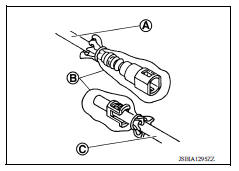
- To keep the connecting portion clean and to avoid damage and foreign materials, cover them completely with plastic bags (B) or something similar.
(A) : Fuel feed hose
(C) : Fuel tube
- Remove center muffler and main muffler. Refer to EX, "Exploded View".
- Disconnect the LH rear park brake cable brackets. Refer to PB, "Exploded View".
- Remove the rear floor insulator located above center and main mufflers.
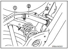
- Disconnect fuel filler hose at fuel filler tube side.
(1) : Fuel filler tube
(2) : Fuel filler hose
(3) : Vent hose
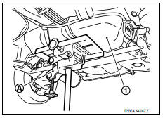
12. Disconnect vent hose from fuel tank side.
13. Support the center part of fuel tank (1) using a suitable jack (A).
14. Remove fuel tank mounting bands (LH/RH).
15. Lower transmission jack carefully to remove fuel tank while holding it by hand.
CAUTION: Fuel tank may be in an unstable condition because of the shape of fuel tank bottom. Be sure to hold tank securely.
INSTALLATION
Installation is in the reverse order of removal.
Fuel Filler Hose
- Insert fuel filler hose to the length below.
Fuel filler hose : 35 mm (1.38 in)
The other hose : 25 mm (0.98 in)
- Be sure hose clamp is not placed on swelled area of fuel filler tube.
- Install fuel filler hose to fuel tank, paying attention to install mark.
- Tighten fuel filler hose clamp so that the remaining length of screw thread becomes to the following.
Fuel tank side hose clamp : 7 - 11 mm (0.28 - 0.43 in)
Fuel filler tube side hose clamp : 8 - 12mm (0.31 - 0.47 in)
EVAP Hose
- Check connections for damage or foreign material.
- Align the matching side connection part with the center of shaft, and insert connector straight until a "click" sound is heard.
Inspection
INSPECTION AFTER INSTALLATION
Use the following procedure to check for fuel leakage.
- Turn ignition switch "ON" (with engine stopped), and check connections for leakage by applying fuel pressure to fuel piping.
- Start engine and rev it up and check there are no fuel leakage at the fuel system tube and hose connections.
 Fuel level sensor unit, fuel filter and fuel pump assembly
Exploded View 1. Lock ring 2. Fuel level sensor unit, fuel filter and fuel pump assembly 3. O-ring 4. Fuel tank Removal and Installation WARNING: Be sure to read "General Precautions" befor ...
EVAP canister
Exploded View 1. EVAP control system pressure sensor 2. O-ring 3. EVAP canister 4. Hose clamp 5. EVAP canister purge hose 6. EVAP vent line 7. O-ring 8. EVAP canister vent control valve 9. EVA ...
Other materials:
Hood
1. Pull the hood lock release handle 1 located
below the instrument panel until the hood
springs up slightly.
2. Locate the lever 2 in between the hood and
grille and push the lever sideways with your
fingertips.
3. Raise the hood 3 .
4. Remove the support rod and insert it into the
...
Readiness for inspection/maintenance (I/M) test
Due to legal requirements in some states and
Canadian Provinces, your vehicle may be required
to be in what is called the "ready condition"
for an Inspection/Maintenance (I/M) test of
the emission control system.
The vehicle is set to the "ready condition" when it
is driven through certain d ...
Categories
- Manuals Home
- Nissan Versa Owners Manual
- Nissan Versa Service Manual
- Video Guides
- Questions & Answers
- External Resources
- Latest Updates
- Most Popular
- Sitemap
- Search the site
- Privacy Policy
- Contact Us

0.0045