Nissan Versa (N17): GPS Antenna
Removal and Installation
REMOVAL
1. Remove the combination meter. Refer to MWI "Removal and Installation" (Type A) or MWI"Removal and Installation" (Type B).
2. Remove the AV control unit. Refer to AV "Removal and Installation".
3. Remove the GPS antenna screw (A), then disconnect the GPS antenna retainer (B).
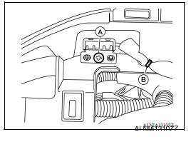
4. Remove the GPS antenna.
INSTALLATION
Installation is in the reverse order of removal.
ANTENNA FEEDER
Feeder Layout
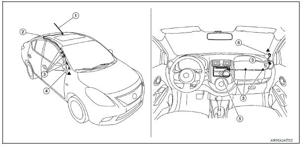
1. Antenna mast 2. Antenna feed 3. Clip 4. Harness connector 5. Audio unit 6. Harness connector
REAR VIEW CAMERA
Removal and Installation
REMOVAL
1. Remove trunk lid finisher. Refer to EXT "Exploded View".
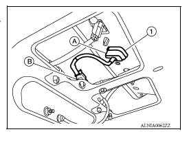
2. Disconnect the harness connector (B) from rear view camera.
3. Press the rear view camera tab (A) and remove the rear view camera (1).
INSTALLATION
Installation is in the reverse order of removal.
 Steering audio control switch
Removal and Installation 1. Steering wheel 2. Steering wheel audio control switches 3. Driver air bag module 4. Steering wheel rear finisher REMOVAL 1. Remove the steering wheel. Refer to ST ...
Precautions
Precaution for Supplemental Restraint System (SRS) "AIR BAG" and "SEAT BELT PRE-TENSIONER" The Supplemental Restraint System such as "AIR BAG" and "SEAT BELT PRE-TENSIONER", us ...
Other materials:
Rear suspension beam
Exploded View
1. Rear suspension beam
Removal and Installation
REMOVAL
Remove the wheel and tire assemblies using power tool. Refer to WT
"Adjustment".
Remove wheel sensor and sensor harness. Refer to BRC "REAR WHEEL SENSOR
: Removal and
Installation".
Re ...
Diagnosis sensor unit
DTC Index
DIAGNOSTIC CODE CHART
NOTE:
Follow the procedures in numerical order when repairing malfunctioning parts.
Confirm whether malfunction is
eliminated using air bag warning lamp or CONSULT each time repair is finished.
If malfunction is still
observed, proceed to the next step. When ...
Categories
- Manuals Home
- Nissan Versa Owners Manual
- Nissan Versa Service Manual
- Video Guides
- Questions & Answers
- External Resources
- Latest Updates
- Most Popular
- Sitemap
- Search the site
- Privacy Policy
- Contact Us

0.0052