Nissan Versa (N17): Headlamp aiming adjustment
Inspection
PREPARATION BEFORE ADJUSTING
CAUTION: Do not use organic solvent (thinner, gasoline etc.)
NOTE:
- For details, refer to the regulations in your own country.
- Perform aiming if the vehicle front body has been repaired and/or the front combination lamp has been replaced.
- Before performing aiming adjustment, check the following:
- Keep all tires inflated to correct pressure.
- Place vehicle on level ground.
- See that vehicle is unloaded (except for full levels of coolant, engine oil and fuel, and spare tire, jack, and tools). Have the driver or equivalent weight placed in driver seat.
- Adjust aiming in the vertical direction by turning the adjusting screw.
- When performing adjustment, if necessary, cover the headlamps and opposite fog lamp. Adjust aiming in the vertical direction by turning the adjusting screw.
AIMING ADJUSTMENT SCREW
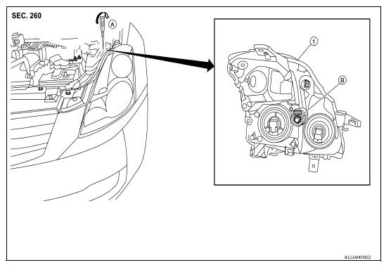
1. Front combination lamp A. Suitable tool (for aiming adjustment) B. Adjusting screw
Aiming Adjustment Procedure
Aiming Adjustment procedure
1. Position the screen.
NOTE:
- Stop the vehicle facing the screen.
- Set the screen so that it is perpendicular to the road.
2. Make the distance between the headlamp center and the screen 7.62 m (25 ft).
3. Start the engine and illuminate the headlamp (LO).
CAUTION: Do not cover the lens surface with tape, etc. because it is made of plastic.
NOTE: Block the light from the headlamp that is not being adjusted with a thick fabric or similar object, so that it does not reach the adjustment screen.
4. Use the adjustment screw to adjust the low beams on the screen, so that it is within the aiming adjustment area.
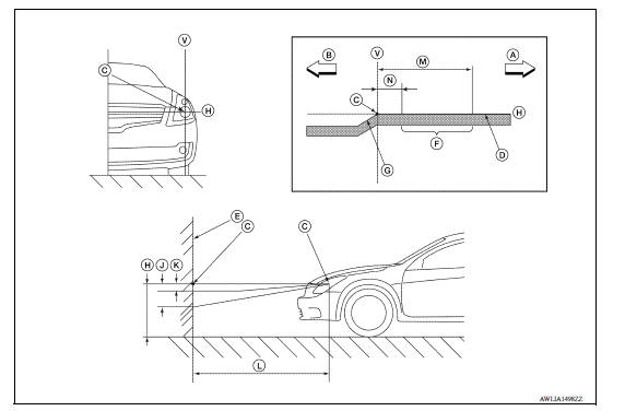
A. Right B. Left C. Center of headlamp bulb (H-V point) D. Cutoff line E. Screen F. Aim evaluation segment G. Step H. Horizontal center line of head lamp J. 53.2 mm (2.09 in) K. -13.3 mm (-0.52 in) L. 7.62 m (25 ft) M. 399 mm (15.71 in) N. 133 mm (5.24 in) V. Vertical center line of headlamp
Basic illuminating area for adjustment should be within the range shown on the aiming chart. Adjust headlamps accordingly.
 Both side front fog lamps are not
turned on
Both side front fog lamps are not
turned on
Description The front fog lamps do not turn ON in any setting. Diagnosis Procedure 1.COMBINATION SWITCH (LIGHTING AND TURN SIGNAL SWITCH) INSPECTION Check the combination switch (lighting and tu ...

Other materials:
Washer tank
Exploded View
1. Washer tank inlet cap 2. Washer tank assembly
Front
Removal and Installation
REMOVAL
1. Remove fender protector. Refer to EXT "Removal and Installation".
2. Disconnect the harness connector from the washer pump.
3. Remove front washer tube.
4. Remove washer ...
CAN Communication circuit
Diagnosis Procedure
1.CONNECTOR INSPECTION
1. Turn the ignition switch OFF.
2. Disconnect the battery cable from the negative terminal.
3. Disconnect all the unit connectors on CAN communication system.
4. Check terminals and connectors for damage, bend and loose connection.
Is the inspectio ...
Categories
- Manuals Home
- Nissan Versa Owners Manual
- Nissan Versa Service Manual
- Video Guides
- Questions & Answers
- External Resources
- Latest Updates
- Most Popular
- Sitemap
- Search the site
- Privacy Policy
- Contact Us

0.0055