Nissan Versa (N17): Steering gear and linkage
Exploded View
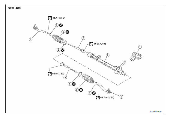
1. Joint cover 2. Steering gear assembly 3. Inner socket 4. Large clamp 5. Boot 6. Small boot clamp 7. Outer socket
Disassembly and Assembly
DISASSEMBLY
- Remove outer socket locknut and outer socket.
- Remove boot clamps and boot.
- Remove inner socket.
ASSEMBLY
- Apply Three Bond 1111B or equivalent to inner socket and turn pinion fully to retract inner socket into gear housing assembly.
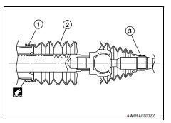
- Install large end (1) of boot (2) to gear housing assembly.
- Install small end (3) of boot (2) to inner socket boot mounting groove.
- Install boot clamp to boot small end.
- Install boot clamp to boot large end using Tool.
CAUTION: Do not reuse boot clamps.
Tool number : KV40107300 ( - )
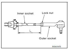
- Adjust inner socket to standard length (L) and then tighten lock nut to the specified torque. Check length of inner socket (L) again after tightening lock nut. Make sure that the length is the standard.
Inner socket length (L) : Refer to ST "Ball Joint Swing Force".
CAUTION: Adjust toe-in after this procedure. The length achieved after toe-in adjustment is not necessarily the above value.
Inspection
INSPECTION AFTER DISASSEMBLY
Boot
- Check boot for cracks and replace it if damage exists.
Steering gear Assembly
- Check steering gear assembly for damage and scratches (inner wall). Replace if there are any abnormal conditions.
Outer Socket and Inner Socket
- Check the following items and replace the component if it does not meet the standard.
BALL JOINT SWINGING FORCE
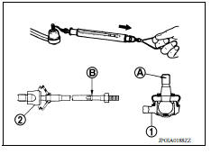
- Hook a Tool at the point shown and pull the spring balance. Make sure that the Tool reads the specified value when ball stud and inner socket start to move. Replace outer socket (1) and inner socket (2) if they are outside the standard.
Tool number : - (J-44372)
Measuring point of outer socket (1) : Ball stud upper side (A)
Measuring point of inner socket (2) : Point (B)
Swinging force : Refer to ST "Ball Joint Swing Force".
BALL JOINT AXIAL END PLAY
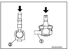
- Apply an axial load of 490 N (50 kg-f, 110 lb-f) to ball stud. Using a dial gauge, measure amount of stud movement and make sure that the value is within the following specified range. Replace outer socket (1) and inner socket (2) if the measured value is outside the standard.
Axial end play : Refer to ST "Ball Joint Axial End Play".
SERVICE DATA AND SPECIFICATIONS (SDS)
General Specifications

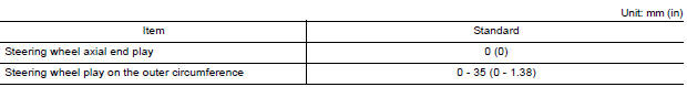
Steering Wheel Axial End Play and Play
Steering Wheel Turning Force

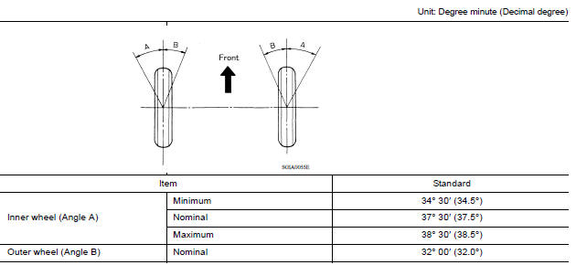
Steering Angle
Steering Column Operating Range
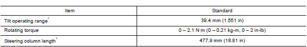
*: For measuring position, refer to ST "Inspection".
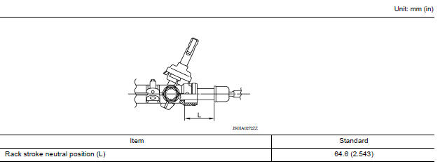
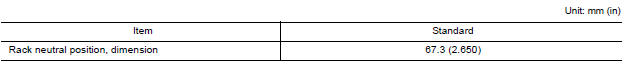
Rack Stroke
Ball Joint Swing Force
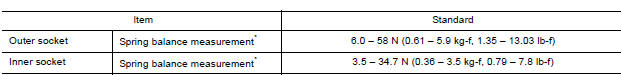
*: For measuring position, refer to ST "Inspection".
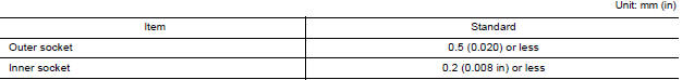
Ball Joint Axial End Play
Inner Socket Length
 Steering gear and linkage
Exploded View 1. Guide 2. Cowl seal 3. Steering gear assembly 4. Front suspension member Front Removal and Installation NOTE: When removing components such as hoses, tubes/lines, etc., cap o ...

Other materials:
Push-button ignition switch (if so equipped)
WARNING
Do not operate the push-button ignition
switch while driving the vehicle except in
an emergency. (The engine will stop when
the ignition switch is pushed 3 consecutive
times in quick succession or the ignition
switch is pushed and held for more
than 2 seconds.) If the engine stops ...
Power supply and ground circuit
Diagnosis Procedure
1.CHECK GROUND CONNECTION
Turn ignition switch OFF.
Check ground connection E. Refer to Ground Inspection in GI, "Circuit
Inspection".
Is the inspection result normal?
YES >> GO TO 2.
NO >> Repair or replace ground connection.
2.CHECK ECM G ...
Categories
- Manuals Home
- Nissan Versa Owners Manual
- Nissan Versa Service Manual
- Video Guides
- Questions & Answers
- External Resources
- Latest Updates
- Most Popular
- Sitemap
- Search the site
- Privacy Policy
- Contact Us

0.0059