Nissan Versa (N17): IPDM E/R
Removal and Installation
CAUTION: IPDM E/R integrated relays are not serviceable parts and must not be removed from the unit.
REMOVAL
1. Disconnect the battery negative terminal. Refer to PG-63, "Removal and Installation".
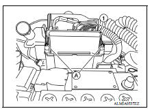
2. Remove the IPDM E/R cover.
3. Release the pawls (A) and separate the IPDM E/R (1) from the case.
4. Disconnect the harness connectors and remove the IPDM E/R.
INSTALLATION
Installation is in the reverse order of removal.
IPDM E/R (WITHOUT I-KEY)
 Power supply and ground circuit
Diagnosis Procedure Regarding Wiring Diagram information, refer to PCS "Wiring Diagram". 1. CHECK FUSE AND FUSIBLE LINKS Check that the following IPDM E/R fuse or fusible links are not ...
Precautions
Precaution for Supplemental Restraint System (SRS) "AIR BAG" and "SEAT BELT PRE-TENSIONER" The Supplemental Restraint System such as "AIR BAG" and "SEAT BELT PRE-TENSIONER", us ...
Other materials:
Combination switch
Exploded View
1. Combination switch 2. Combination switch harness connector
Front
Removal and Installation
CAUTION:
Before servicing, disconnect both battery terminals and wait at
least three minutes.
Do not use air tools or electric tools for servicing.
REMOVAL
1. Disconnect p ...
Combination meter
Removal and Installation
REMOVAL
1. Disconnect the negative battery terminal. Refer to PG "Removal and
Installation".
2. Remove cluster lid A. Refer to IP "Removal and Installation".
3. Remove the combination meter screws.
4. Pull the combination meter straight out to di ...
Categories
- Manuals Home
- Nissan Versa Owners Manual
- Nissan Versa Service Manual
- Video Guides
- Questions & Answers
- External Resources
- Latest Updates
- Most Popular
- Sitemap
- Search the site
- Privacy Policy
- Contact Us

0.0047