Nissan Versa (N17): Structure and operation
TRANSAXLE
TRANSAXLE : Cross-Sectional View
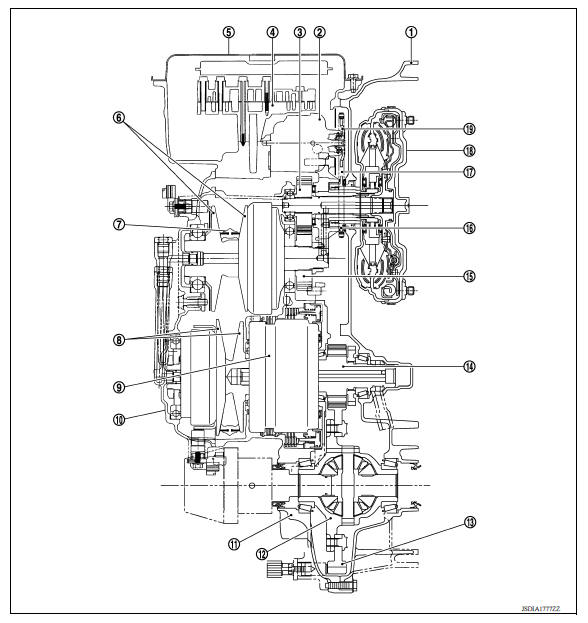
1. Converter housing 2. Oil pump 3. Counter drive gear 4. Control valve 5. Oil pan 6. Primary pulley 7. Steel belt 8. Secondary pulley 9. Planetary gear (auxiliary gearbox) 10. Side cover 11. Transaxle case 12. Differential case 13. Final gear 14. Reduction gear 15. Counter driven gear 16. Drive sprocket 17. Oil pump chain 18. Torque converter 19. Driven sprocket
TRANSAXLE : Transaxle Mechanism
BELT & PULLEY
Mechanism
It is composed of a pair of pulleys (the groove width is changed freely in the axial direction) and the steel belt (the steel plates are placed continuously and the belt is guided with the multilayer steel rings on both sides).
The groove width changes according to wrapping radius of steel belt and pulley from low status to overdrive status continuously with non-step. It is controlled with the oil pressures of primary pulley and secondary pulley.
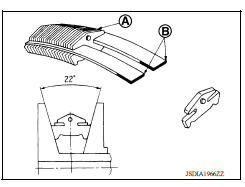
Steel belt
It is composed of multiple steel plates (A) and two steel rings (B) stacked to a several number. The feature of this steel belt transmits power with compression of the steel plate in contrast with transmission of power in pulling with a rubber belt. Friction force is required with the pulley slope to transmit power from the steel plate. The force is generated with the following mechanism: Oil pressure applies to the secondary pulley to nip the plate. ⇒The plate is pushed and extended outward. ⇒The steel ring shows withstands.
⇒Pulling force is generated on the steel ring. ⇒The plate of the primary pulley is nipped between the pulley. ⇒Friction force is generated between the steel belt and the pulley.
Therefore, responsibilities are divided by the steel plate that transmits the power with compression and the steel ring that maintains necessary friction force. In this way, the tension of the steel ring is distributed on the entire surface and stress variation is limited, resulting in good durability.
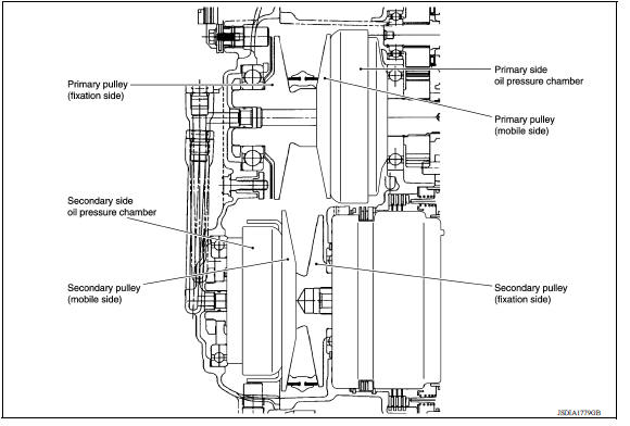
Pulley
The primary pulley (input shaft side) and the secondary pulley (output shaft side) have the shaft with slope (fixed cone surface), movable sheave (movable cone surface that can move in the axial direction) and oil pressure chamber at the back of the movable sheave.The primary pulley (input shaft side) and the secondary pulley (output shaft side) have the shaft with slope (fixed cone surface), movable sheave (movable cone surface that can move in the axial direction) and oil pressure chamber at the back of the movable sheave.
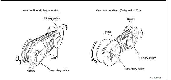
Pulley gear shifting operation
- Pulley gear shifting operation
The movable sheave slides on the shaft to change the groove width of the pulley. Input signals of engine load (accelerator pedal opening), engine revolution and gear ratio (vehicle speed) change the operation pressures of the primary pulley and the secondary pulley, and controls the pulley groove width. Along with change of the pulley groove width, the belt contact radius is changed. This allows continuous and stepless gear shifting from low to overdrive. "The contact radius ratio of each pulley in contact with the belt x auxiliary gearbox gear ratio" is the gear ratio.
AUXILIARY GEARBOX MECHANISM
1st, 2nd and reverse gears are changed with the planetary gear mechanism.
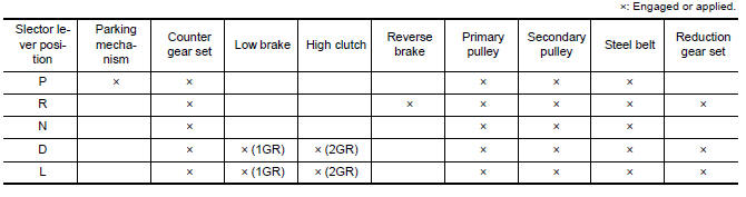
TRANSAXLE : Operation Status
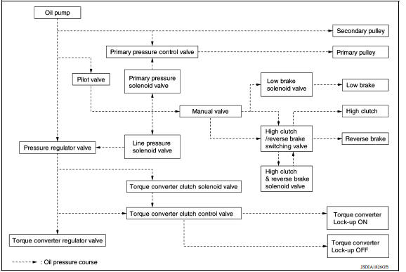
TRANSAXLE : Oil Pressure System
Oil pressure required for operation of the transaxle transmission mechanism is generated by oil pump, oil pressure control valve, solenoid valve, etc.
TRANSAXLE : Component Description
| Part name | Function |
| Torque converter | It is composed of the cover converter, turbine assembly, stator, pump impeller assembly, etc. It increases the engine torque and transmits the power to the transaxle. |
| Oil pump | Through the oil pump drive chain, it uses the vane oil pump driven by the engine. It generates necessary oil pressure to circulate fluid and to operate the clutch and brake. |
| Counter gear set | The power from the torque converter is transmitted to the primary pulley through the counter drive gear and the counter driven gear. |
| Belt & pulley (Continuously variable transmission) | It is composed of the primary pulley, secondary pulley, steel belt, etc. and the mechanism performs shifting, changes the gear ratio and transmits the power with oil pressure from the control valve. |
| Auxiliary gearbox (stepped transmission) | It is composed of the planetary gear, multi-disc clutch, multi-disc brake, etc. and the mechanism performs shifting (1-2 gear shifting and reverse) with oil pressure from the control valve. |
| Reduction gear set | Conveys power from the transmission mechanism to the reduction gear and the final gear. |
| Parking mechanism | When the shift lever is changed to P position, the mechanism fixes the parking gear (integrated with the reduction gear) and the fixes the output shaft. |
| Control valve | Controls oil pressure from the oil pump to the pressure suitable for the line pressure control system, shift control system, lock-up control system and lubrication system. |
| Pressure regulator valve | Adjusts the discharge pressure from the oil pump to the optimum pressure (line pressure) corresponding to the driving condition. |
| Torque converter regulator valve | Adjusts the feed pressure to the torque converter to the optimum pressure corresponding to the driving condition. |
| Pilot valve | Adjusts line pressure and produces a constant pressure (pilot pressure) necessary for activating each solenoid valve. |
| Manual valve | Distributes the clutch and brake operation pressures (pilot pressure) corresponding to each shift position. |
| High clutch/reverse brake switching valve | Switches the circuit for the high clutch and the reverse brake. |
| Torque converter clutch control valve | It is operated with the torque converter clutch solenoid valve and it adjusts the tightening pressure and non-tightening pressure of the torque converter clutch piston of the torque converter |
| Primary pressure control valve | It is operated with the primary pressure solenoid valve and adjusts the feed pressure to the primary pulley. |
| Primary pressure solenoid valve | TM "CVT CONTROL SYSTEM : Primary Pressure Solenoid Valve" |
| Low brake solenoid valve | TM "CVT CONTROL SYSTEM : Low Brake Solenoid Valve" |
| High clutch & reverse brake solenoid valve | TM "CVT CONTROL SYSTEM : High Clutch & Reverse Brake Solenoid Valve" |
| Torque converter clutch solenoid valve | TM "CVT CONTROL SYSTEM : Torque Converter Clutch Solenoid Valve" |
| Line pressure solenoid valve | TM "CVT CONTROL SYSTEM : Line Pressure Solenoid Valve" |
 Shift lock system
SHIFT LOCK SYSTEM : Component Parts Location 1. Stop lamp switch 2. Shift lock release lever 3. Park position switch 4. Shift lock solenoid Component Function Stop lamp switc ...
Fluid cooler & fluid warmer system
FLUID COOLER & FLUID WARMER SYSTEM : System Description CVT FLUID COOLER SCHEMATIC COMPONENT DESCRIPTION CVT Oil Warmer The CVT oil warmer (1) is installed on the front part of trans ...
Other materials:
Electric ignition system
ELECTRIC IGNITION SYSTEM : System Diagram
ELECTRIC IGNITION SYSTEM : System Description
INPUT/OUTPUT SIGNAL CHART
Sensor
Input signal to ECM
ECM function
Actuator
Crankshaft position sensor (POS)
Engine speed*3
Piston position
Ignition timing control
Igni ...
P0733 3GR Incorrect ratio
Description
This malfunction is detected when the A/T does not shift into 3GR position as
instructed by TCM. This is not
only caused by electrical malfunction (circuits open or shorted) but by
mechanical malfunction such as control
valve sticking, improper solenoid valve operation, etc.
DTC ...
Categories
- Manuals Home
- Nissan Versa Owners Manual
- Nissan Versa Service Manual
- Video Guides
- Questions & Answers
- External Resources
- Latest Updates
- Most Popular
- Sitemap
- Search the site
- Privacy Policy
- Contact Us

0.0049