Nissan Versa (N17): Electric ignition system
ELECTRIC IGNITION SYSTEM : System Diagram
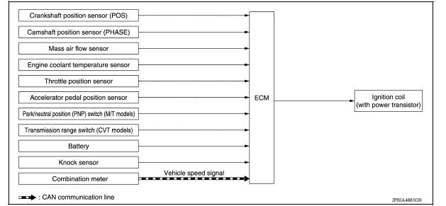
ELECTRIC IGNITION SYSTEM : System Description
INPUT/OUTPUT SIGNAL CHART
| Sensor | Input signal to ECM | ECM function | Actuator |
| Crankshaft position sensor (POS) | Engine speed*3 Piston position | Ignition timing control | Ignition coil (with power transistor) |
| Camshaft position sensor (PHASE) | |||
| Mass air flow sensor | Amount of intake air | ||
| Engine coolant temperature sensor | Engine coolant temperature | ||
| Throttle position sensor | Throttle position | ||
| Accelerator pedal position sensor | Accelerator pedal position | ||
| Park/neutral position (PNP) switch*1 | PNP signal | ||
| Transmission range switch*2 | |||
| Battery | Battery voltage*3 | ||
| Knock sensor | Engine knocking | ||
| Combination meter | Vehicle speed*4 |
*1: M/T models *2: A/T models or CVT models *3: ECM determines the start signal status by the signals of engine speed and battery voltage.
*4: This signal is sent to the ECM through CAN communication line.
SYSTEM DESCRIPTION
Firing order: 1 3 4 2 The ignition timing is controlled by the ECM to maintain the best airfuel ratio for every running condition of the engine. The ignition timing data is stored in the ECM.
The ECM receives information such as the injection pulse width and camshaft position sensor signal. Computing this information, ignition signals are transmitted to the power transistor.
During the following conditions, the ignition timing is revised by the ECM according to the other data stored in the ECM.
- At starting
- During warmup
- At idle
- At low battery voltage
- During acceleration
The knock sensor retard system is designed only for emergencies. The basic ignition timing is programmed within the antiknocking zone, if recommended fuel is used under dry conditions. The retard system does not operate under normal driving conditions. If engine knocking occurs, the knock sensor monitors the condition.
The signal is transmitted to the ECM. The ECM retards the ignition timing to eliminate the knocking condition.
 Multiport fuel injection system
MULTIPORT FUEL INJECTION SYSTEM : System Diagram MULTIPORT FUEL INJECTION SYSTEM : System Description INPUT/OUTPUT SIGNAL CHART Sensor Input signal to ECM ECM function Actuato ...
Air conditioning cut control
AIR CONDITIONING CUT CONTROL : System Diagram AIR CONDITIONING CUT CONTROL : System Description INPUT/OUTPUT SIGNAL CHART Sensor Input signal to ECM ECM function Actuator ...
Other materials:
Control linkage
Exploded View
1. Shifter lever A 2. Selector lever 3. Selector cable
4. Shifter cable 5. Cable mounting bracket 6. Tapping bolt
7. Bracket 8. Grommet 9. M/T shift selector assembly
10. Shift selector 11. Shift selector handle
Removal and Installation
REMOVAL
Move the shift selector to ...
U0140 Lost communication (BCM)
Description
CAN (Controller Area Network) is a serial communication line for real-time
application. It is an on-vehicle multiplex
communication line with high data communication speed and excellent malfunction
detection ability.
Many electronic control units are equipped onto a vehicle, and ...
Categories
- Manuals Home
- Nissan Versa Owners Manual
- Nissan Versa Service Manual
- Video Guides
- Questions & Answers
- External Resources
- Latest Updates
- Most Popular
- Sitemap
- Search the site
- Privacy Policy
- Contact Us

0.0059