Nissan Versa (N17): Multiport fuel injection system
MULTIPORT FUEL INJECTION SYSTEM : System Diagram
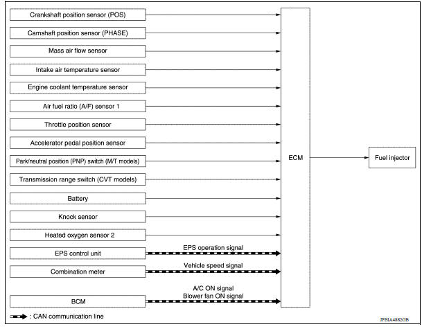
MULTIPORT FUEL INJECTION SYSTEM : System Description
INPUT/OUTPUT SIGNAL CHART
| Sensor | Input signal to ECM | ECM function | Actuator |
| Crankshaft position sensor (POS) | Engine speed*4 Piston position | Fuel injection & mixture ratio control | Fuel injector |
| Camshaft position sensor (PHASE) | |||
| Mass air flow sensor | Amount of intake air | ||
| Intake air temperature sensor | Intake air temperature | ||
| Engine coolant temperature sensor | Engine coolant temperature | ||
| Air fuel ratio (A/F) sensor 1 | Density of oxygen in exhaust gas | ||
| Throttle position sensor | Throttle position | ||
| Accelerator pedal position sensor | Accelerator pedal position | ||
| Park/neutral position (PNP) switch*1 | PNP signal | ||
| Transmission range switch*2 | |||
| Battery | Battery voltage*4 | ||
| Knock sensor | Engine knocking condition | ||
| Heated oxygen sensor 2*3 | Density of oxygen in exhaust gas | ||
| EPS control unit | EPS operation signal*5 | ||
| Combination meter | Vehicle speed*5 | ||
| BCM | A/C ON signal*5 Blower fan signal*5 |
*1: M/T models *2: A/T models or CVT models *3: This sensor is not used to control the engine system under normal conditions.
*4: ECM determines the start signal status by the signals of engine speed and battery voltage.
*5: This signal is sent to the ECM through CAN communication line.
SYSTEM DESCRIPTION
The amount of fuel injected from the fuel injector is determined by the ECM. The ECM controls the length of time the valve remains open (injection pulse duration). The amount of fuel injected is a program value in the ECM memory. The program value is preset by engine operating conditions. These conditions are determined by input signals (for engine speed and intake air) from the crankshaft position sensor, camshaft position sensor and the mass air flow sensor.
VARIOUS FUEL INJECTION INCREASE/DECREASE COMPENSATION
In addition, the amount of fuel injected is compensated to improve engine performance under various operating conditions as listed below.
<Fuel increase>
- During warmup
- When starting the engine
- During acceleration
- Hotengine operation
- When selector lever position is changed from N to D (A/T models or CVT models)
- Highload, highspeed operation
<Fuel decrease>
- During deceleration
- During high engine speed operation
MIXTURE RATIO FEEDBACK CONTROL (CLOSED LOOP CONTROL)
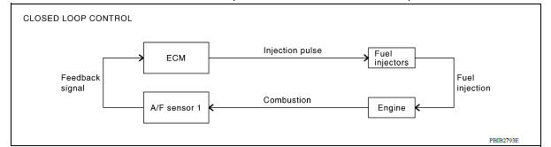
The mixture ratio feedback system provides the best airfuel mixture ratio for drivability and emission control.
The three way catalyst (manifold) can better reduce CO, HC and NOx emissions. This system uses A/F sensor 1 in the exhaust manifold to monitor whether the engine operation is rich or lean. The ECM adjusts the injection pulse width according to the sensor voltage signal. This maintains the mixture ratio within the range of stoichiometric (ideal airfuel mixture).
This stage is referred to as the closed loop control condition.
Heated oxygen sensor 2 is located downstream of the three way catalyst (manifold). Even if the switching characteristics of A/F sensor 1 shift, the airfuel ratio is controlled to stoichiometric by the signal from heated oxygen sensor 2.
- Open Loop Control The open loop system condition refers to when the ECM detects any of the following conditions. Feedback control stops in order to maintain stabilized fuel combustion.
- Deceleration and acceleration
- Highload, highspeed operation
- Malfunction of A/F sensor 1 or its circuit
- Insufficient activation of heated sensor 1 at low engine coolant temperature
- High engine coolant temperature
- During warmup
- After shifting from N to D (A/T models or CVT models)
- When starting the engine
MIXTURE RATIO SELFLEARNING CONTROL
The mixture ratio feedback control system monitors the mixture ratio signal transmitted from A/F sensor 1.
This feedback signal is then sent to the ECM. The ECM controls the basic mixture ratio as close to the theoretical mixture ratio as possible. However, the basic mixture ratio is not necessarily controlled as originally designed. Both manufacturing differences (i.e., mass air flow sensor hot wire) and characteristic changes during operation (i.e., fuel injector clogging) directly affect mixture ratio.
Accordingly, the difference between the basic and theoretical mixture ratios is monitored in this system. This is then computed in terms of "injection pulse duration" to automatically compensate for the difference between the two ratios.
"Fuel trim" refers to the feedback compensation value compared against the basic injection duration. Fuel trim includes "shortterm fuel trim" and "longterm fuel trim".
"Shortterm fuel trim" is the shortterm fuel compensation used to maintain the mixture ratio at its theoretical value. The signal from A/F sensor 1 indicates whether the mixture ratio is RICH or LEAN compared to the theoretical value. The signal then triggers a reduction in fuel volume if the mixture ratio is rich, and an increase in fuel volume if it is lean.
"Longterm fuel trim" is overall fuel compensation carried out longterm to compensate for continual deviation of the "shortterm fuel trim" from the central value. Such deviation will occur due to individual engine differences, wear over time and changes in the usage environment.
FUEL INJECTION TIMING
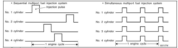
Two types of systems are used.
- Sequential Multiport Fuel Injection System Fuel is injected into each cylinder during each engine cycle according to the firing order. This system is used when the engine is running.
- Simultaneous Multiport Fuel Injection System
Fuel is injected simultaneously into all four cylinders twice each engine
cycle. In other words, pulse signals
of the same width are simultaneously transmitted from the ECM.
The four injectors will then receive the signals two times for each engine cycle.
This system is used when the engine is being started and/or if the fail safe system (CPU) is operating.
FUEL SHUTOFF
Fuel to each cylinder is cut off during deceleration, operation of the engine at excessively high speeds or operation of the vehicle at excessively high speeds.
 Engine control system
ENGINE CONTROL SYSTEM : System Diagram NOTE: Battery current sensor is used in CVT models. ENGINE CONTROL SYSTEM : System Description ECM performs various controls such as fuel injection cont ...
Electric ignition system
ELECTRIC IGNITION SYSTEM : System Diagram ELECTRIC IGNITION SYSTEM : System Description INPUT/OUTPUT SIGNAL CHART Sensor Input signal to ECM ECM function Actuator Cran ...
Other materials:
If your vehicle overheats
If your vehicle is overheating (indicated by an
extremely high temperature gauge reading (if so
equipped), a red high temperature warning light
(if so equipped) ), or if you feel a
lack of
engine power, detect abnormal noise, etc. take
the following steps.
WARNING
Do not continue to driv ...
U1001 CAN comm circuit
Description
CAN (Controller Area Network) is a serial communication line for real time
application. It is an onvehicle multiplex
communication line with high data communication speed and excellent error
detection ability. Many electronic
control units are equipped onto a vehicle, and each con ...
Categories
- Manuals Home
- Nissan Versa Owners Manual
- Nissan Versa Service Manual
- Video Guides
- Questions & Answers
- External Resources
- Latest Updates
- Most Popular
- Sitemap
- Search the site
- Privacy Policy
- Contact Us

0.0053