Nissan Versa (N17): Water pump
Exploded View
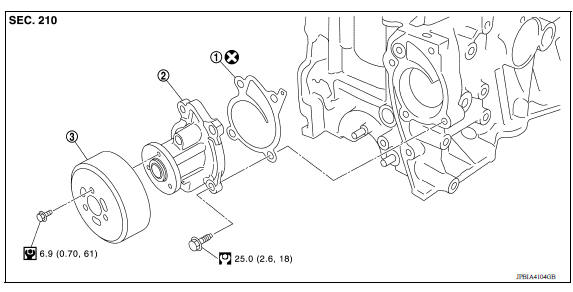
1. Gasket 2. Water pump 3. Water pump pulley
Removal and Installation
REMOVAL
CAUTION:
Do not remove the radiator cap when the engine is hot. Serious burns could occur from highpressure engine coolant escaping from the radiator. Wrap a thick cloth around the radiator cap. Slowly turn it a quarter of a turn to release builtup pressure. Carefully remove radiator cap by turning it all the way.
- Drain engine coolant from radiator.
CAUTION:
- Perform this step when the engine is cold.
- Do not spill engine coolant on drive belt.
- Remove front wheel and tire (RH).
- Remove front fender protector (RH).
- Loosen water pump pulley bolts before loosening belt tension of drive belt.
- Remove drive belt.
- Remove water pump pulley.
- Remove water pump.
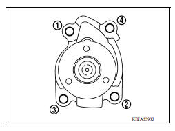
- Loosen water pump bolts in reverse order as shown.
- Engine coolant will leak from cylinder block, so have a receptacle
ready below.
CAUTION: - Do not allow water pump vane to contact any other parts.
- Water pump cannot be disassembled and must be replaced as an assembly.
INSPECTION AFTER REMOVAL
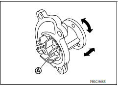
- Visually check for significant dirt or rust on the water pump body and vane (A) and replace as necessary.
- Check that the vane shaft turns smoothly by hand and is not excessively loose.
- Replace the water pump assembly if the water pump does not perform properly.
INSTALLATION
Installation is in the reverse order of removal.
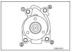
- Tighten water pump bolts in order as shown.
CAUTION:
- Do not allow the water pump vane to contact any other parts.
- Water pump cannot be disassembled and must be replaced as an assembly.
- Do not reuse gasket.
- Sealing surface must be clean and free of dents or flaws.
INSPECTION AFTER INSTALLATION
- Before starting engine, check oil/fluid levels, including engine coolant and engine oil. If less than required quantity, fill to the specified level.
- Use procedure below to check for fuel leakage.
- Turn ignition switch ON (with engine stopped). With fuel pressure applied to fuel piping, check for fuel leakage at connection points.
- Start engine. With engine speed increased, check again for fuel leakage at connection points.
- Run engine to check for unusual noise and vibration.
NOTE:
If hydraulic pressure inside timing chain tensioner drops after removal and installation, slack in the guide may generate a pounding noise during and just after engine start. However, this is normal. Noise will stop after hydraulic pressure rises.
- Warm up engine thoroughly to make sure there is no leakage of fuel, exhaust gas, or any oils/fluids, including engine oil and engine coolant.
- Bleed air from passages in lines and hoses, such as in cooling system.
- fter cooling down engine, again check oil/fluid levels, including engine oil and engine coolant. Refill to specified level, if necessary.
- Summary of the inspection items:
| Item | Before starting engine | Engine running | After engine stopped | |
| Engine coolant | Level | Leakage | Level | |
| Engine oil | Level | Leakage | Level | |
| Transmission/ transaxle fluid | A/T and CVT Models | Leakage | Level/Leakage | Leakage |
| M/T Models | Level/Leakage | Leakage | Level/Leakage | |
| Other oils and fluids* | Level | Leakage | Level | |
| Fuel | Leakage | Leakage | Leakage | |
| Exhaust gas | Leakage | |||
*Power steering fluid, brake fluid, etc.
 Cooling fan
Exploded View 1. Fan shroud 2. Fan motor 3. Cooling fan A. Cooling fan nut L. Genuine NISSAN high strength locking sealant ...
Thermostat
Exploded View 1. Radiator hose (lower) 2. Water inlet 3. Rubber ring 4. Thermostat A. To radiator Removal and Installation WARNING: Do not remove the radiator cap when the engine is hot. Serio ...
Other materials:
Meters and gauges
Type A (if so equipped)
1. Tachometer
2. Speedometer
3. Fuel gauge
4. Odometer
Twin trip odometer
Trip computer
5. Continuously Variable Transmission
(CVT) position indicator (if so equipped)
Automatic Transmission (A/T) position
indicator (if so equipped)
6. Instrument brightness con ...
Wiper and washer switch
Switch operation
Type A (if so equipped)
The windshield wiper and washer operates when
the ignition switch is in the ON position.
Push the lever down to operate the wiper at the
following speed:
Intermittent (INT) - intermittent operation
can be adjusted by turning the knob toward
...
Categories
- Manuals Home
- Nissan Versa Owners Manual
- Nissan Versa Service Manual
- Video Guides
- Questions & Answers
- External Resources
- Latest Updates
- Most Popular
- Sitemap
- Search the site
- Privacy Policy
- Contact Us

0.0049