Nissan Versa (N17): Thermostat
Exploded View
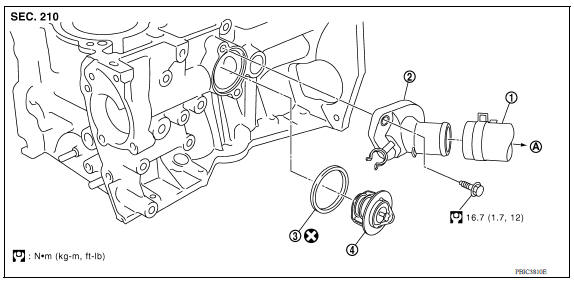
1. Radiator hose (lower) 2. Water inlet 3. Rubber ring 4. Thermostat A. To radiator
Removal and Installation
WARNING:
Do not remove the radiator cap when the engine is hot. Serious burns could occur from highpressure engine coolant escaping from the radiator. Wrap a thick cloth around the radiator cap. Slowly turn it a quarter of a turn to release builtup pressure. Carefully remove radiator cap by turning it all the way.
REMOVAL
- Drain engine coolant from radiator.
CAUTION: - Perform this step when engine is cold.
- Do not spill engine coolant on drive belt.
- Remove air duct.
- Remove oil level gauge and guide.
- Disconnect radiator hose (lower) from water inlet.
- Remove water inlet, thermostat, and rubber ring.
NOTE: Engine coolant will leak from cylinder block, so have a receptacle ready below.
INSPECTION AFTER REMOVAL
Thermostat
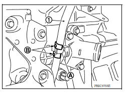
- Place a thread (A) so that it is caught in the valves of thermostat (1). Immerse fully in a container (B) filled with water. Heat while stirring.
- The valve opening temperature is the temperature at which the valve opens and falls from the thread.
- Continue heating. Check the full open valve lift amount.
- After checking the maximum valve lift amount, lower the water temperature and check the valve closing temperature.
- If out of the standard specification range, replace the thermostat.
INSTALLATION
Installation is in the reverse order of removal.
Thermostat
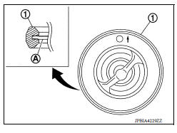
- Install thermostat making sure rubber ring (1) groove fits securely
to thermostat flange (A).
CAUTION: Do not reuse rubber ring.
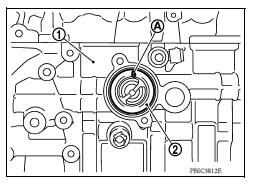
- Install thermostat (2) into the cylinder block (1) with jiggle valve (A) facing upward.
Water Inlet After installation, attach the water inlet clip (A) on the oil level gauge guide (1) positioned at location (B) as shown.
INSPECTION AFTER INSTALLATION
- Before starting engine, check oil/fluid levels, including engine coolant and engine oil. If less than required quantity, fill to the specified level.
- Use procedure below to check for fuel leakage.
- Turn ignition switch ON (with engine stopped). With fuel pressure applied to fuel piping, check for fuel leakage at connection points.
- Start engine. With engine speed increased, check again for fuel leakage at connection points.
- Run engine to check for unusual noise and vibration.
NOTE: If hydraulic pressure inside timing chain tensioner drops after removal and installation, slack in the guide may generate a pounding noise during and just after engine start. However, this is normal. Noise will stop after hydraulic pressure rises.
- Warm up engine thoroughly to make sure there is no leakage of fuel, exhaust gas, or any oils/fluids, including engine oil and engine coolant.
- Bleed air from passages in lines and hoses, such as in cooling system.
- After cooling down engine, again check oil/fluid levels, including engine oil and engine coolant. Refill to specified level, if necessary.
- Summary of the inspection items:
| Item | Before starting engine | Engine running | After engine stopped | |
| Engine coolant | Level | Leakage | Level | |
| Engine oil | Level | Leakage | Level | |
| Transmission/ transaxle fluid | A/T and CVT Models | Leakage | Level/Leakage | Leakage |
| M/T Models | Level/Leakage | Leakage | Level/Leakage | |
| Other oils and fluids* | Level | Leakage | Level | |
| Fuel | Leakage | Leakage | Leakage | |
| Exhaust gas | Leakage | |||
 Water pump
Exploded View 1. Gasket 2. Water pump 3. Water pump pulley Removal and Installation REMOVAL CAUTION: Do not remove the radiator cap when the engine is hot. Serious burns could occur from hi ...
Water outlet
Exploded View M/T models 1. Engine coolant temperature sensor 2. Clamp 3. Gasket 4. Clamp 5. Bracket 6. Clamp 7. Water outlet 8. Clamp 9. Clamp 10. Cylinder block heater (Canada) A. From elect ...
Other materials:
Fuel injector and fuel tube
Exploded View
1. Stud bolt 2. Oring (green) 3. Fuel injector (front) 4. Clip 5. Fuel
injector (rear) 6. Oring (black) 7. Fuel tube protector 8. Fuel tube 9. Clamp
10. Quick connector cap (engine side) 11. Fuel feed hose 12. Quick connector cap
(floor pipingside) 13. Fuel connector protect ...
P0711 Transmission fluid temperature
sensor A
DTC Logic
DTC DETECTION LOGIC
DTC
Trouble diagnosis name
DTC detection condition
Possible causes
P0711
Transmission Fluid Temperature
Sensor "A" Circuit Range/
Performance
Under the following diagnosis
conditions, A/T fluid temperature
does not rise to ...
Categories
- Manuals Home
- Nissan Versa Owners Manual
- Nissan Versa Service Manual
- Video Guides
- Questions & Answers
- External Resources
- Latest Updates
- Most Popular
- Sitemap
- Search the site
- Privacy Policy
- Contact Us

0.0056