Nissan Versa (N17): IPDM E/R (Intelligent power distribution module engine room)
Reference Value
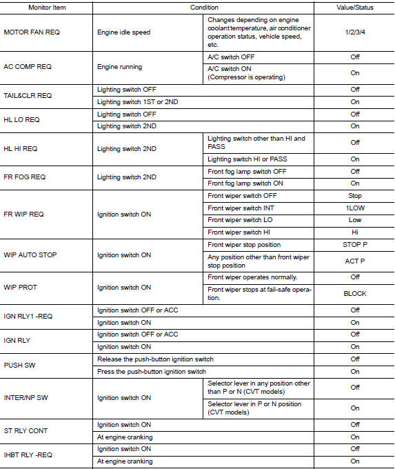
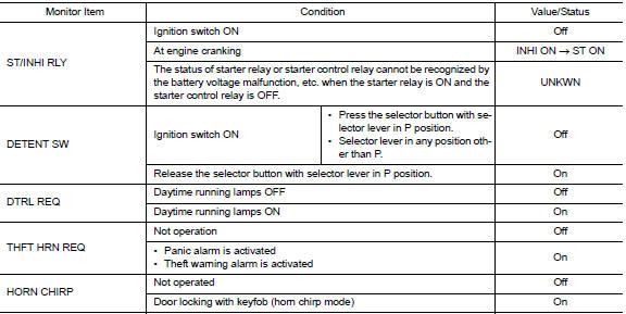
VALUES ON THE DIAGNOSIS TOOL
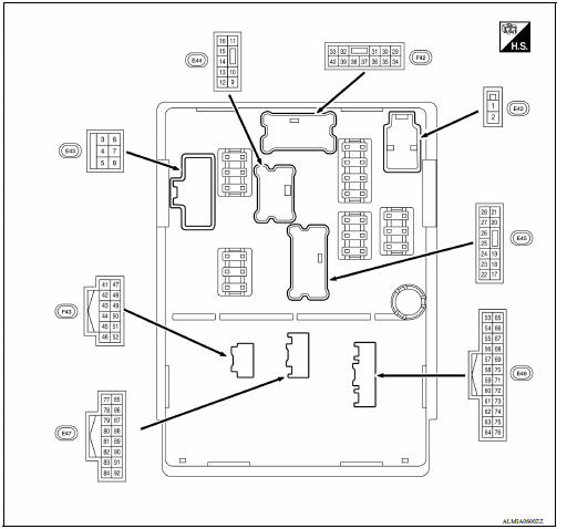
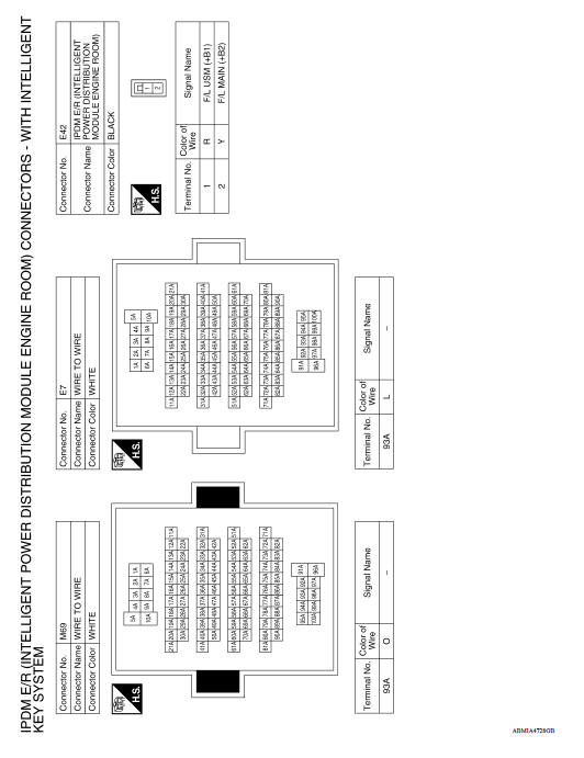
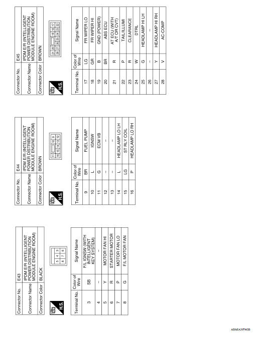
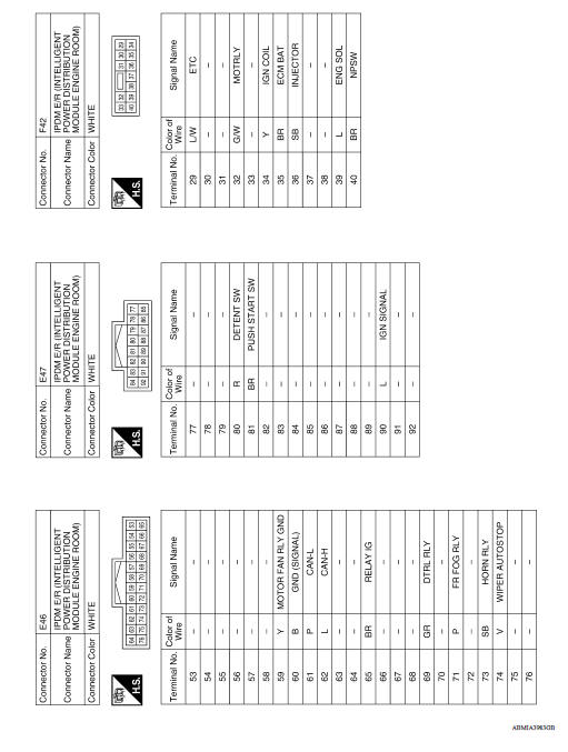
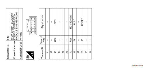
TERMINAL LAYOUT
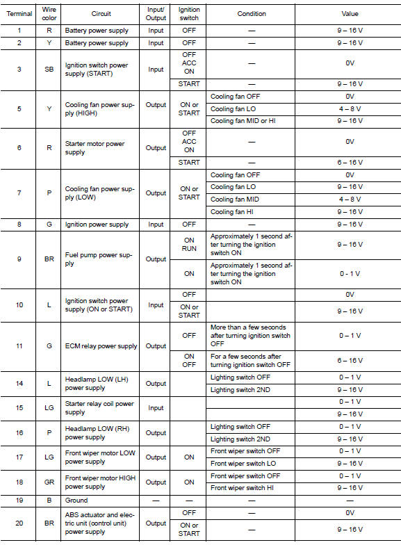
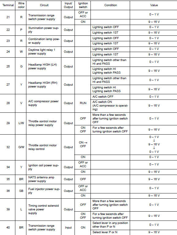
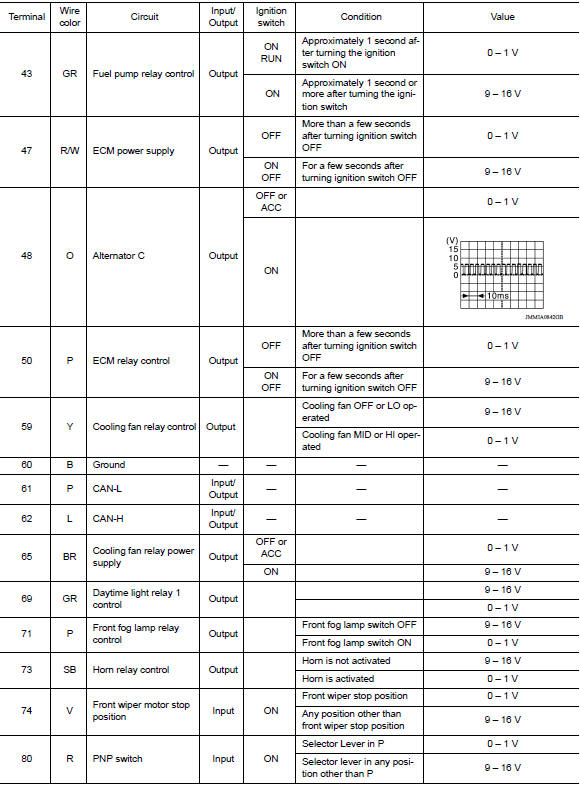
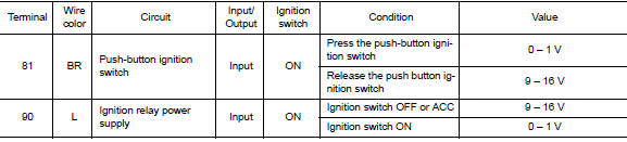
PHYSICAL VALUES
Fail-safe
CAN COMMUNICATION CONTROL
When CAN communication with ECM and BCM is impossible, IPDM E/R performs fail-safe control. After CAN communication recovers normally, it also returns to normal control.
If No CAN Communication Is Available With ECM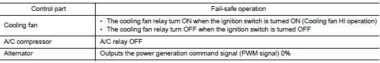
If No CAN Communication Is Available With BCM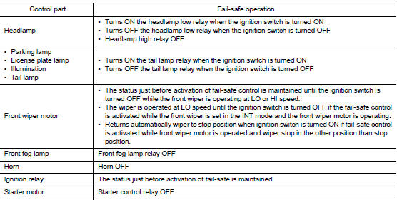
IGNITION RELAY MALFUNCTION DETECTION FUNCTION
- IPDM E/R monitors the voltage at the contact circuit and excitation coil circuit of the ignition relay inside it.
- IPDM E/R judges the ignition relay error if the voltage differs between the contact circuit and the excitation coil circuit.
- If the ignition relay cannot turn OFF due to contact seizure, it
activates the tail lamp relay for 10 minutes to
alert the user to the ignition relay malfunction when the ignition switch is
turned OFF.
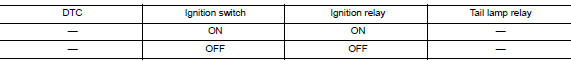

NOTE: The tail lamp turns OFF when the ignition switch is turned ON.
FRONT WIPER CONTROL
IPDM E/R detects front wiper stop position by a front wiper auto stop signal.
When a front wiper auto stop signal is in the conditions listed below, IPDM
E/R stops power supply to wiper
after repeating a front wiper 10 second activation and 20 second stop five
times.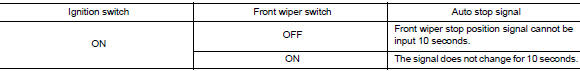
NOTE: This operation status can be confirmed on the IPDM E/R "Data Monitor" that displays "BLOCK" for the item "WIP PROT" while the wiper is stopped.
STARTER MOTOR PROTECTION FUNCTION
IPDM E/R turns OFF the starter control relay to protect the starter motor when the starter control relay remains active for 90 seconds.
DTC Index
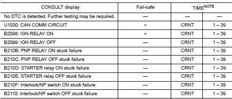
NOTE: The details of TIME display are as follows.
- CRNT: The malfunctions that are detected now
- 1 - 39: The number is indicated when it is normal at present and a malfunction was detected in the past. It increases like 0 → 1 → 2 * * * 38 → 39 after returning to the normal condition whenever IGN OFF → ON. It is fixed to 39 until the self-diagnosis results are erased if it is over 39. It returns to 0 when a malfunction is detected again in the process.
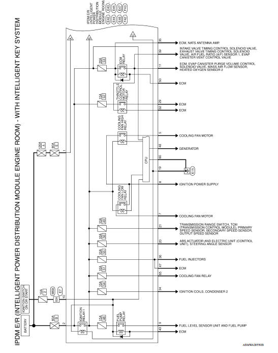
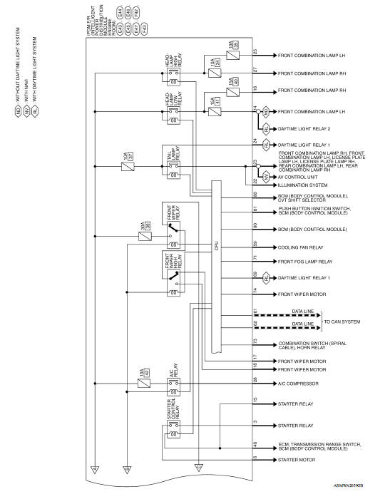
WIRING DIAGRAM
IPDM E/R (INTELLIGENT POWER DISTRIBUTION MODULE ENGINE ROOM)
Wiring Diagram
DTC/CIRCUIT DIAGNOSIS
 Diagnosis system (IPDM E/R)
Diagnosis Description AUTO ACTIVE TEST Description In auto active test, the IPDM E/R sends a drive signal to the following systems to check their operation. Front wiper (LO, HI) Parking l ...
U1000 CAN Comm circuit
Description Refer to LAN"CAN COMMUNICATION SYSTEM : System Description". DTC Logic DTC DETECTION LOGIC Diagnosis Procedure 1. PERFORM SELF DIAGNOSTIC RESULT 1. Turn ignition switch O ...
Other materials:
Oil pan (upper) and oil strainer
Exploded View
1. Rear oil seal 2. Oring 3. Oil pan (upper)
4. Oil pump chain tensioner (for oil
pump drive chain)
5. Oil pump drive chain 6. Crankshaft key
7. Crankshaft sprocket 8. Oil pump sprocket 9. Oil pump
10. Oring 11. Oring 12. Oil pan drain plug
13. Drain plug washer 14. Oil pan ...
CVT Fluid cooler system
Cleaning
Whenever an automatic transaxle is repaired, overhauled, or replaced, the CVT
fluid cooler mounted in the
radiator must be inspected and cleaned.
Metal debris and friction material, if present, can be trapped or be deposited
in the CVT fluid cooler. This
debris can contaminate th ...
Categories
- Manuals Home
- Nissan Versa Owners Manual
- Nissan Versa Service Manual
- Video Guides
- Questions & Answers
- External Resources
- Latest Updates
- Most Popular
- Sitemap
- Search the site
- Privacy Policy
- Contact Us

0.0054