Nissan Versa (N17): U1000 CAN Comm circuit
Description
Refer to LAN"CAN COMMUNICATION SYSTEM : System Description".
DTC Logic
DTC DETECTION LOGIC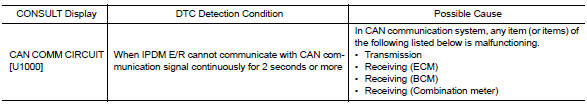
Diagnosis Procedure
1. PERFORM SELF DIAGNOSTIC RESULT
1. Turn ignition switch ON and wait for 2 second or more.
2. Check "SELF-DIAG RESULTS" of IPDM E/R.
Is "CAN COMM CIRCUIT" displayed?
YES >> Refer to LAN "Trouble Diagnosis Flow Chart".
NO >> Refer to GI "Intermittent Incident".
 IPDM E/R (Intelligent power distribution
module engine room)
IPDM E/R (Intelligent power distribution
module engine room)
Reference Value VALUES ON THE DIAGNOSIS TOOL TERMINAL LAYOUT PHYSICAL VALUES Fail-safe CAN COMMUNICATION CONTROL When CAN communication with ECM and BCM is impossible ...
B2098 Ignition relay on stuck
Description IPDM E/R operates the ignition relay when it receives an ignition switch ON signal from BCM via CAN communication. Turn the ignition relay OFF by pressing the push-button igniti ...
Other materials:
P0711 Transmission fluid temperature
sensor A
DTC Logic
DTC DETECTION LOGIC
DTC
Trouble diagnosis name
DTC detection condition
Possible causes
P0711
Transmission Fluid Temperature
Sensor "A" Circuit Range/
Performance
Under the following diagnosis
conditions, A/T fluid temperature
does not rise to ...
Main power supply and ground circuit
Diagnosis Procedure
1.CHECK TCM POWER CIRCUIT 1
Turn the ignition switch OFF.
Disconnect the TCM connector.
Check the voltage between the TCM harness connector terminals and
ground.
Is the inspection result normal?
YES >> GO TO 2.
NO >> GO TO 4.
2.CHECK TCM POWER ...
Categories
- Manuals Home
- Nissan Versa Owners Manual
- Nissan Versa Service Manual
- Video Guides
- Questions & Answers
- External Resources
- Latest Updates
- Most Popular
- Sitemap
- Search the site
- Privacy Policy
- Contact Us

0.0055