Toyota
Nissan Versa
 Sedan Service Manual
Transmission & driveline » Transaxle & transmission (TM)
Key interlock cable

Exploded View

Exploded View

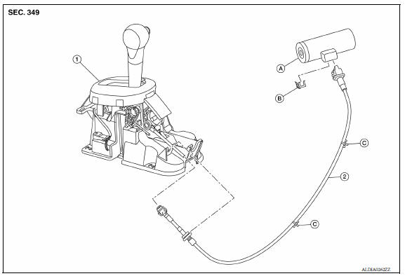
1. A/T shift selector assembly 2. Key interlock cable A: Key cylinder B: Lock plate C: Clip

Removal and Installation

CAUTION: Always apply the parking brake before performing removal and installation.

REMOVAL

  1. Move the shift selector to the "N" position.
  2. Remove the shift selector handle. Refer to TM "Disassembly and Assembly".
  3. Remove the center console. Refer to IP "Removal and Installation".
  4. Move the shift selector to the "P" position.
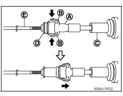
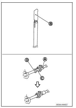
  5. Press the pawls (B) of the key interlock cable slider (A) while sliding it in the direction of the casing cap (C), and separate the adjusting holder (D) and slider.

(E) : Key interlock rod

  1. Remove the key interlock cable from the shift selector assembly.
  2. Remove the instrument lower panel LH. Refer to IP "Removal and Installation".
  3. Remove the steering column upper and lower covers. Refer to ST "Exploded View".
  4. Remove the center console lower (if equipped). Refer to IP "Removal and Installation".

REMOVAL

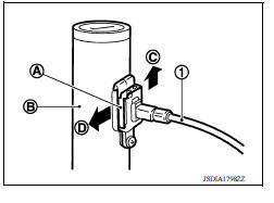
  1. Lift lock plate (A) in the direction of the arrow ( C) and remove in the direction of the arrow ( D).
  2. Remove the key interlock cable from the key cylinder.
  3. Disengage the clips and remove the key interlock cable from the vehicle.

(1) : Key interlock cable

(B) : Key cylinder

REMOVAL

INSTALLATION

Installation is in the reverse order of removal.

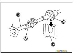
  • Temporarily install the adjust holder (A) to the key interlock rod (B).
  • Install the casing cap (C) to the cable bracket (D) on the shift selector assembly.

CAUTION:

  • Do not bend or twist key interlock cable excessively when installing.
  • After installing key interlock cable to cable bracket (D) on shift selector assembly, make sure casing cap (C) is firmly secured in cable bracket (D) on shift selector assembly.
  • If casing cap (C) is loose [less than 39.2 N (4.0 kg, 8.8 lb) removing force], replace key interlock cable.

INSTALLATION

  • Slide the slider (A) toward the key interlock rod (D) while pressing the pull lock (B) down to securely connect the adjust holder (C) with the key interlock rod (D).

        CAUTION:

  • Do not press tabs when holding slider (A).
  • Do not apply any side-to-side force to key interlock rod (D) when sliding slider (A).

INSTALLATION

Inspection

INSPECTION AFTER INSTALLATION

  • Check the A/T operation. If a malfunction is found, adjust the A/T position. Refer to TM "Inspection and Adjustment".
  • Make sure the key can be removed only when the shift selector is in the "P" position.
  • Make sure the ignition switch will not turn to LOCK position when the shift selector is not in the "P" position.
    More about «Transaxle & transmission (TM)»:

    Precautions

    Structure and operation

    Position switch

    Gear oil

    Side oil seal

    Position switch

    Control linkage

    Air breather hose

    5Th main gear assembly

    Transaxle assembly

    Transaxle assembly

    Input shaft and gear

    Mainshaft and gear

    Final drive

    Precautions

    A/T Control system

    A/T Shift lock system

    Transaxle

    A/T control system

    Line pressure control

    Shift change control

    Lock-up control

    Diagnosis description

    Consult function

    TCM

    Diagnosis and repair work flow

    Additional service when replacing TCM

    Additional service when replacing transaxle assembly

    A/T Fluid cooler

    Stall test

    Line pressure test

    U0073 Communication bus a off

    U0100 Lost communication (ECM A)

    U0140 Lost communication (BCM)

    U0155 Lost communication (IPC)

    U0300 Can communication data

    U1000 Can comm circuit

    U1117 Lost communication (ABS)

    P062F EEPROM

    P0705 Transmission range switch A

    P0706 Transmission range sensor A

    P0711 Transmission fluid temperature sensor A

    P0712 Transmission fluid temperature sensor A

    P0713 Transmission fluid temperature sensor A

    P0717 Input speed sensor A

    P0720 Output speed sensor

    P072C Stuck in 1GR

    P072D Stuck in 2GR

    P072E Stuck in 3GR

    P072F Stuck in 4GR

    P0731 1GR Incorrect ratio

    P0732 2GR Incorrect ratio

    P0733 3GR Incorrect ratio

    P0734 4GR Incorrect ratio

    P073E Unable to engage r range

    P073F Unable to engage 1GR

    P0740 Torque converter

    P0743 Torque converter

    P0744 Torque converter

    P074A Unable to engage 2GR

    P074B Unable to engage 3GR

    P074C Unable to engage 4GR

    P0863 TCM Communication

    P0890 TCM

    P0962 Pressure control solenoid A

    P0963 Pressure control solenoid A

    P0973 Shift solenoid A

    P0974 Shift solenoid A

    P0976 Shift solenoid B

    P0977 Shift solenoid B

    P0979 Shift solenoid C

    P0980 Shift solenoid C

    P0982 Shift solenoid D

    P0983 Shift solenoid D

    P2760 Torque converter

    Main power supply and ground circuit

    Overdrive control switch

    O/D OFF indicator lamp

    Shift position indicator circuit

    Shift lock system

    A/T Fluid

    A/T Shift selector

    Control cable

    Key interlock cable

    TCM

    Oil pan

    Output speed sensor

    Differential side oil seal

    Fluid cooler tube

    Transmission assembly

    Service data and specifications (SDS)

    Precautions

    Component parts

    Shift lock system

    Structure and operation

    Fluid cooler & fluid warmer system

    CVT Control system

    Line pressure control

    Shift control

    Lock-up control

    Idle neutral control

    Diagnosis system (TCM)

    TCM

    Diagnosis and repair work flow

    Additional service when replacing TCM

    Additional service when replacing transaxle assembly

    Calibration of G Sensor

    CVT Fluid cooler system

    Stall test

    Line pressure test

    U0073 Communication bus A off

    U0100 Lost communication (ECM A)

    U0140 Lost communication (BCM)

    U0141 Lost communication (BCM A)

    U0155 Lost communication (IPC)

    U0300 Can communication data

    U1000 Can COMM circuit

    U1117 Lost communication (ABS)

    P062F EEPROM

    P0705 Transmission range sensor A

    P0706 Transmission range sensor A

    P0711 Transmission fluid temperature sensor A

    P0712 Transmission fluid temperature sensor A

    P0713 Transmission fluid temperature sensor A

    P0715  Input speed sensor A

    P0720 Output speed sensor

    P0740 Torque converter

    P0743 Torque converter

    P0744 Torque converter

    P0746 Pressure control solenoid A

    P0846 Transmission fluid pressure SEN/SW B

    P0847 Transmission fluid pressure SEN/SW B

    P0848 Transmission fluid pressure SEN/SW B

    P0863 TCM Communication

    P0890 TCM

    P0962 Pressure control solenoid A

    P0963 Pressure control solenoid A

    P0965 Pressure control solenoid B

    P0966 Pressure control solenoid B

    P0967 Pressure control solenoid B

    P0998 Shift solenoid F

    P0999 Shift solenoid F

    P099B Shift solenoid G

    P099C Shift solenoid G

    P1586 G Sensor

    P1588 G Sensor

    P2765 Clutch B speed sensor

    P2857 Clutch A pressure

    P2858 Clutch B pressure

    P2859 Clutch A pressure

    P285A Clutch B pressure

    Main power supply and ground circuit

    Overdrive control switch

    OD OFF indicator lamp

    Shift position indicator circuit

    Shift lock system

    CVT Control system

    CVT Fluid

    CVT Shift selector

    Control cable

    Key interlock cable

    TCM

    Air breather hose

    G Sensor

    Oil pan

    Primary speed sensor

    Secondary speed sensor

    Output speed sensor

    Differential side oil seal

    Water hose

    Fluid cooler hose

    PLUG

    Transmission assembly

    Service data and specifications (SDS)

    Nissan Versa Sedan Service Manual / Transmission & driveline / Transaxle & transmission (TM) / Key interlock cable

    Nissan Versa Sedan Service Manual

    Categories


    © 2017-2024 Copyright www.niveguide.com