Nissan Versa (N17): Lock-up control
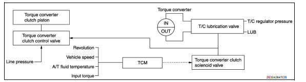
Lock-up control : system diagram
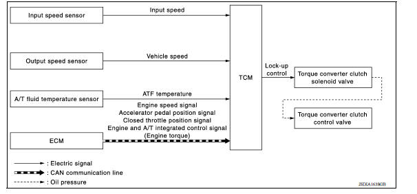
Lock-up control : system description
- The torque converter clutch piston in the torque converter is engaged to eliminate torque converter slip to increase power transmission efficiency.
- The torque converter clutch control valve operation is controlled by the torque converter clutch solenoid valve, which is controlled by a signal from TCM, and the torque converter clutch control valve engages or releases the torque converter clutch piston.
Lock-up Operation Condition Table 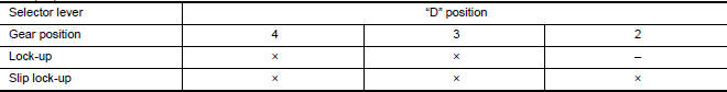
Lock-up released
- In the lock-up released state, the torque converter clutch control valve
is set into the unlocked state by the
torque converter clutch solenoid and the lock-up apply pressure is drained.
in this way, the torque converter clutch piston is not coupled.
Lock-up Applied
- In the lock-up applied state, the torque converter clutch control valve
is set into the locked state by the
torque converter clutch solenoid and lock-up apply pressure is generated.
In this way, the torque converter clutch piston is pressed and coupled.
Smooth Lock-up Control
When shifting from the lock-up released state to the lock-up applied state, the current output to the torque converter clutch solenoid is controlled with the TCM. In this way, when shifting to the lock-up applied state, the torque converter clutch is temporarily set to the half-clutched state to reduce the shock.
Half-clutched State
- The current output from the TCM to the torque converter clutch solenoid
is varied to steadily increase the
torque converter clutch solenoid pressure.
In this way, the lock-up apply pressure gradually rises and while the torque converter clutch piston is put into half-clutched states, the torque converter clutch piston operating pressure is increased and the coupling is completed smoothly.
Slip Lock-up Control
- In the slip region, the torque converter clutch solenoid current is
controlled with the TCM to put it into the
half-clutched state. This absorbs the engine torque fluctuation and lock-up
operates from low speed.
This raises the fuel efficiency for 2GR, 3GR, and 4GR.
On board diagnostic (OBD) system
Description
This system is an on board diagnostic system that records exhaust emission-related diagnostic information and detects a sensors/actuator-related malfunction. A malfunction is indicated by the malfunction indicator lamp (MIL) and stored in ECU memory as a DTC. The diagnostic information can be obtained with the diagnostic tool (GST: Generic Scan Tool).
OBD function
When GST is connected with a data link connector equipped on the vehicle side, it will communicate with the control unit equipped in the vehicle and then enable various kinds of diagnostic tests. Refer to TM, "Description".
NOTE: Service $0A is not applied for regions where it is not mandated.
 Shift change control
Shift change control : system diagram Shift change control : system description The clutch is controlled with the optimum timing and oil pressure by the engine speed, engine torque infor ...

Other materials:
Variable voltage control system (if so equipped)
CAUTION
Do not ground accessories directly to
the battery terminal. Doing so will bypass
the variable voltage control system
and the vehicle battery may not
charge completely.
Use electrical accessories with the engine
running to avoid discharging the
vehicle battery.
Your v ...
U0140 Lost communication (BCM)
DTC Logic
DTC DETECTION LOGIC
DTC
Trouble diagnosis name
DTC detection condition
Possible causes
U0140
Lost Communication With Body
Control Module
When the ignition switch is ON,
TCM is unable to receive the
CAN communications signal
from BCM continuously ...
Categories
- Manuals Home
- Nissan Versa Owners Manual
- Nissan Versa Service Manual
- Video Guides
- Questions & Answers
- External Resources
- Latest Updates
- Most Popular
- Sitemap
- Search the site
- Privacy Policy
- Contact Us

0.0054