Nissan Versa (N17): Power supply and ground circuit
Diagnosis Procedure
Regarding Wiring Diagram information, refer to BCS "Wiring Diagram".
1.CHECK FUSES AND FUSIBLE LINK
Check that the following fuses and fusible link are not blown.
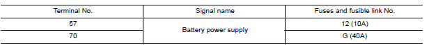
Is the fuse blown?
YES >> Replace the blown fuse or fusible link after repairing the affected circuit.
NO >> GO TO 2.
2.CHECK POWER SUPPLY CIRCUIT
- Disconnect BCM connector M99.
- Check voltage between BCM connector M99 and ground.
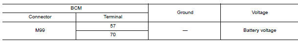
Is the inspection result normal?
YES >> GO TO 3.
NO >> Repair harness or connector.
3.CHECK GROUND CIRCUIT
Check continuity between BCM connector M99 and ground.

Is the inspection result normal?
YES >> Inspection End.
NO >> Repair harness or connector.
 B2628 Outside antenna
Combination meter buzzer
Component Function Check 1.CHECK FUNCTION Select INTELLIGENT KEY of BCM using CONSULT. Select INSIDE BUZZER in ACTIVE TEST mode. Touch Key, Knob or Take Out to check that it works normally. ...
Other materials:
Door lock function
DOOR LOCK FUNCTION : System Description
SYSTEM DIAGRAM
DOOR REQUEST SWITCH OPERATION
When pressing the request switch, it is possible to lock and unlock the door
by carrying the Intelligent Key.
OPERATION DESCRIPTION
When the BCM detects that each door request switch is pressed, it s ...
Power door lock system symptoms
Symptom Table
DOOR LOCK/UNLOCK FUNCTION MALFUNCTION
NOTE:
Before performing the diagnosis in the following table, check "WORK
FLOW". Refer to DLK "Work
Flow".
Check that vehicle is under the condition shown in "Conditions of
vehicle" before starting diagnosis, and
check e ...
Categories
- Manuals Home
- Nissan Versa Owners Manual
- Nissan Versa Service Manual
- Video Guides
- Questions & Answers
- External Resources
- Latest Updates
- Most Popular
- Sitemap
- Search the site
- Privacy Policy
- Contact Us

0.0047