Nissan Versa (N17): Main line between IPDM-E and DLC circuit
Diagnosis Procedure
1.CHECK CONNECTOR
1. Turn the ignition switch OFF.
2. Disconnect the battery cable from the negative terminal.
3. Check the following terminals and connectors for damage, bend and loose connection (connector side and harness side).
- Harness connector E7
- Harness connector M69
Is the inspection result normal?
YES >> GO TO 2.
NO >> Repair the terminal and connector.
2.CHECK HARNESS CONTINUITY (OPEN CIRCUIT)
1. Disconnect the following harness connectors.
- IPDM E/R
- Harness connectors E7 and M69
2. Check the continuity between the IPDM E/R harness connector and the
harness connector.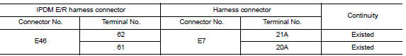
Is the inspection result normal?
YES >> GO TO 3.
NO >> Repair the main line between the IPDM E/R and the harness connector E7.
3.CHECK HARNESS CONTINUITY (OPEN CIRCUIT)
Check the continuity between the harness connector and the data link
connector.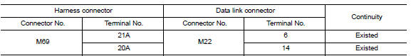
Is the inspection result normal?
YES (Present error)>>Check CAN system type decision again.
YES (Past error)>>Error was detected in the main line between the IPDM E/R and the data link connector.
NO >> Repair the main line between the harness connector M69 and the data link connector.
 CAN Communication circuit
Diagnosis Procedure 1.CONNECTOR INSPECTION 1. Turn the ignition switch OFF. 2. Disconnect the battery cable from the negative terminal. 3. Disconnect all the unit connectors on CAN communication s ...
ECM Branch line circuit
Diagnosis Procedure 1.CHECK CONNECTOR 1. Turn the ignition switch OFF. 2. Disconnect the battery cable from the negative terminal. 3. Check the terminals and connectors of the ECM for damage, bend ...
Other materials:
Cooling fan control
Cooling fan control : system diagram
Cooling fan control : system description
INPUT/OUTPUT SIGNAL CHART
Sensor
Input signal to ECM
ECM function
Actuator
Crankshaft position sensor (POS)
Camshaft position sensor (PHASE)
Engine speed*1
Piston position
Cool ...
Service data and specifications
(SDS)
Idle Speed
*: Under the following conditions
A/C switch: OFF
Electric load: OFF (Lights, heater fan & rear window defogger)
Steering wheel: Kept in straight-ahead position
Ignition Timing
*: Under the following conditions
A/C switch: OFF
Ele ...
Categories
- Manuals Home
- Nissan Versa Owners Manual
- Nissan Versa Service Manual
- Video Guides
- Questions & Answers
- External Resources
- Latest Updates
- Most Popular
- Sitemap
- Search the site
- Privacy Policy
- Contact Us

0.0065