
Nissan Versa (N17): P1226 TP sensor
DTC Logic
DTC DETECTION LOGIC
| DTC No. | Trouble diagnosis | DTC detecting condition | Possible cause |
| P1226 | Closed throttle position learning performance | Closed throttle position learning is not performed successfully, repeatedly. | Electric throttle control actuator (TP sensor 1 and 2) |
DTC CONFIRMATION PROCEDURE
1.PRECONDITIONING
If DTC Confirmation Procedure has been previously conducted, always perform the following procedure before conducting the next test.
- Turn ignition switch OFF and wait at least 10 seconds.
- Turn ignition switch ON.
- Turn ignition switch OFF and wait at least 10 seconds.
TESTING CONDITION: Before performing the following procedure, confirm that battery voltage is more than 10 V at idle.
>> GO TO 2.
2.PERFORM DTC CONFIRMATION PROCEDURE
- Turn ignition switch ON.
- Turn ignition switch OFF and wait at least 10 seconds.
- Turn ignition switch ON.
- Repeat steps 2 and 3 for 32 times.
- Check 1st trip DTC.
Is 1st trip DTC detected?
YES >> Go to EC, "Diagnosis Procedure".
NO >> INSPECTION END
Diagnosis Procedure
1.CHECK ELECTRIC THROTTLE CONTROL ACTUATOR VISUALLY
- Turn ignition switch OFF.
- Remove the intake air duct. Refer to EM, "Removal and Installation".
- Check if foreign matter is caught between the throttle valve (1) and the housing.
-
 : Vehicle front
Is the inspection result normal?
YES >> GO TO 2.
NO >> Remove the foreign matter and clean the electric throttle control actuator inside, and then perform throttle valve closed position learning. Refer to EC, "Work Procedure".
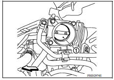
2.REPLACE ELECTRIC THROTTLE CONTROL ACTUATOR
Replace electric throttle control actuator. Refer to EM, "Removal and Installation".
>> INSPECTION END
 P1225 TP sensor
Other materials:
U0155 Lost communication (IPC)
DTC Logic
DTC DETECTION LOGIC
DTC
Trouble diagnosis name
DTC detection condition
Possible causes
U0155
Lost Communication With Instrument
Panel Cluster (IPC)
Control Module
When the ignition switch is ON,
TCM is unable to receive the
CAN communications ...
Diagnosis system [abs actuator
and electric unit (control unit)]
CONSULT Function (ABS)
APPLICATION ITEMS
CONSULT can display each diagnostic item using the following direct
diagnostic modes.
ECU IDENTIFICATION
ABS actuator and electric unit (control unit) part number is displayed.
SELF DIAGNOSTIC RESULT
Operation Procedure
Before p ...
Categories
- Manuals Home
- Nissan Versa Owners Manual
- Nissan Versa Service Manual
- Video Guides
- Questions & Answers
- External Resources
- Latest Updates
- Most Popular
- Sitemap
- Search the site
- Privacy Policy
- Contact Us

0.0074