
Nissan Versa (N17): Performance test
Inspection
INSPECTION PROCEDURE
- Connect recovery/recycling/recharging equipment (for HFC-134a) or manifold gauge.
- Start the engine, and set to the following condition.
Test condition
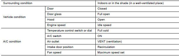
- Maintain test condition until A/C system becomes stable. (Approximately 10 minutes)
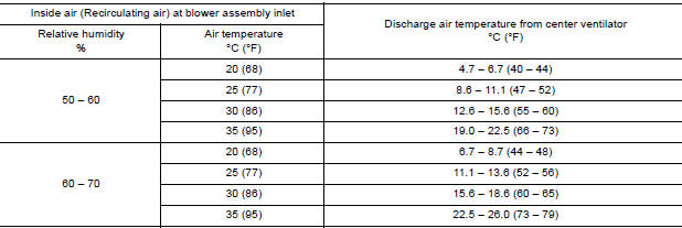
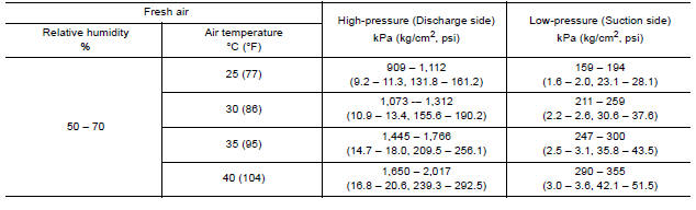
- Check that test results of "recirculating-to-discharge air temperature" and "ambient air temperature-tooperating pressure" are within the specified value.
- When test results are within the specified value, inspection is
complete.
If any test result is out of the specified value, perform diagnosis by gauge pressure. Refer to HA "Symptom Table".
RECIRCULATING-TO-DISCHARGE AIR TEMPERATURE TABLE
AMBIENT AIR TEMPERATURE-TO-OPERATING PRESSURE TABLE
SYMPTOM DIAGNOSIS
HEATER AND AIR CONDITIONING SYSTEM SYMPTOMS
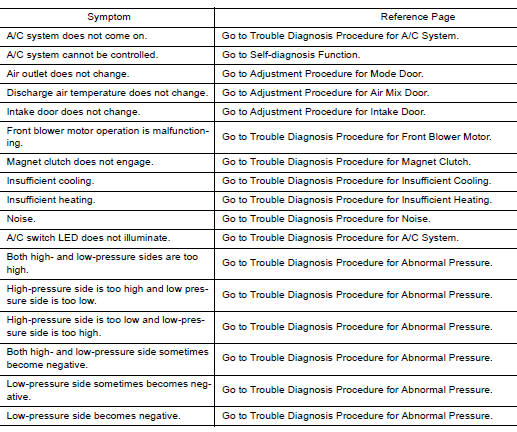
Symptom Table
SYMPTOM TABLE
REFRIGERATION SYSTEM SYMPTOMS
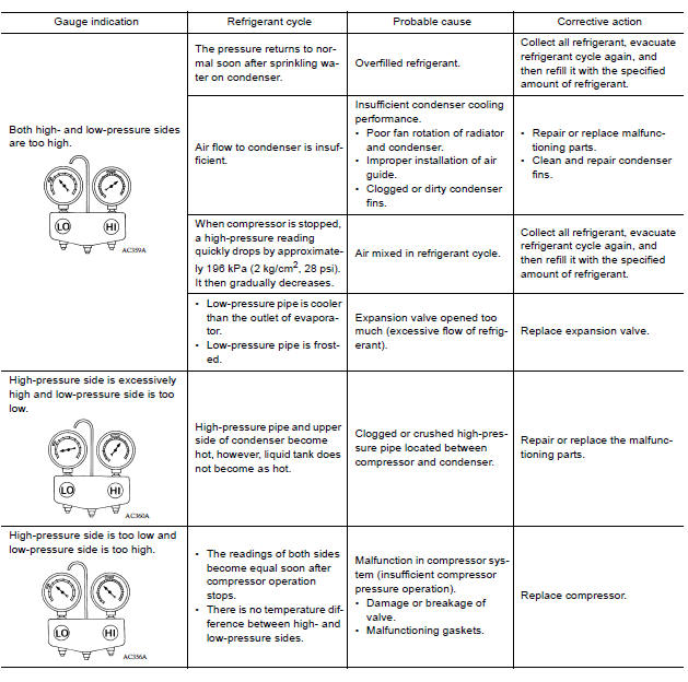
Trouble Diagnosis For Unusual Pressure
Diagnose using a manifold gauge whenever system's high and/or low side pressure(s) is/are unusual. The marker above the gauge scale in the following tables indicates the standard (usual) pressure range. Refer to Ambient air temperature-to-operating pressure table since the standard (usual) pressure, differs from vehicle to vehicle.
Symptom Table
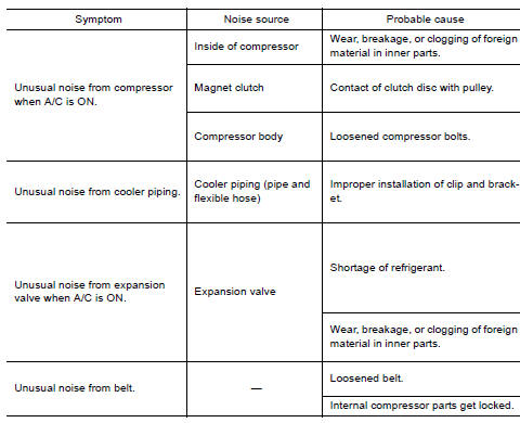
NOISE
Symptom Table
REMOVAL AND INSTALLATION
 Oil
Oil
Description MAINTENANCE OF OIL LEVEL The compressor oil is circulating in the system together with the refrigerant. It is necessary to fill compressor with oil when replacing A/C system parts or ...
Compressor
Exploded View 1. Compressor Removal and Installation CAUTION: Perform oil return operation before each refrigeration system disassembly. However, if a large amount of refrigerant or oil i ...
Other materials:
Tire pressure monitoring system
TIRE PRESSURE MONITORING SYSTEM : System Diagram
TIRE PRESSURE MONITORING SYSTEM : System
Description
The BCM has pressure judgment and trouble diagnosis functions. When the
BCM detects low inflation pressure
or another unusual symptom, the low tire pressure warning lamp in the
c ...
Parking brake switch
Component Function Check
1.CHECK PARKING BRAKE SWITCH OPERATION
Check that brake warning lamp in combination meter turns ON/OFF when parking
brake is actuated.
Is the inspection result normal?
YES >> Inspection End.
NO >> Proceed to diagnosis procedure. Refer to BRC "Diagno ...
Categories
- Manuals Home
- Nissan Versa Owners Manual
- Nissan Versa Service Manual
- Video Guides
- Questions & Answers
- External Resources
- Latest Updates
- Most Popular
- Sitemap
- Search the site
- Privacy Policy
- Contact Us

0.008