Nissan Versa (N17): Structure and operation
Positive Crankcase Ventilation
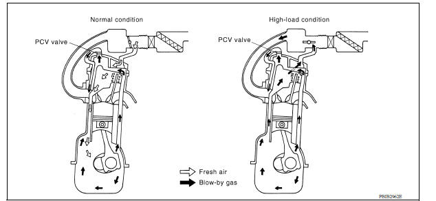
This system returns blowby gas to the intake manifold.
The positive crankcase ventilation (PCV) valve is provided to conduct crankcase blowby gas to the intake manifold.
During partial throttle operation of the engine, the intake manifold sucks the blowby gas through the PCV valve.
Normally, the capacity of the valve is sufficient to handle any blowby and a small amount of ventilating air.
The ventilating air is then drawn from the air inlet tubes into the crankcase. In this process the air passes through the hose connecting air inlet tubes to rocker cover.
Under fullthrottle condition, the manifold vacuum is insufficient to draw the blowby flow through the valve.
The flow goes through the hose connection in the reverse direction.
On vehicles with an excessively high blowby, the valve does not meet the requirement. This is because some of the flow will go through the hose connection to the air inlet tubes under all conditions.
On Board Refueling Vapor Recovery (ORVR)
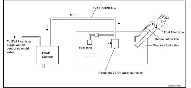
From the beginning of refueling, the air and vapor inside the fuel tank go through refueling EVAP vapor cut valve and EVAP/ORVR line to the EVAP canister. The vapor is absorbed by the EVAP canister and the air is released to the atmosphere.
When the refueling has reached the full level of the fuel tank, the refueling EVAP vapor cut valve is closed and refueling is stopped because of auto shutoff. The vapor which was absorbed by the EVAP canister is purged during driving.
WARNING:
When conducting inspections below, be sure to observe the following:
- Put a "CAUTION: FLAMMABLE" sign in workshop.
- Do not smoke while servicing fuel system. Keep open flames and sparks away from work area.
- Be sure to furnish the workshop with a CO2 fire extinguisher.
CAUTION:
- Before removing fuel line parts, carry out the following procedures:
- Put drained fuel in an explosionproof container and put lid on securely.
- Release fuel pressure from fuel line.
- Disconnect battery ground cable.
- Always replace Oring when the fuel gauge retainer is removed.
- Do not kink or twist hose and tube when they are installed.
- Do not tighten hose and clamps excessively to avoid damaging hoses.
- After installation, run engine and check for fuel leaks at connection.
- Do not attempt to top off the fuel tank after the fuel pump nozzle shuts off automatically.
Continued refueling may cause fuel overflow, resulting in fuel spray and possibly a fire.
 Engine control system
ENGINE CONTROL SYSTEM : Component Parts Location 1. Mass air flow sensor (with intake air temperature sensor) 2. Electric throttle control actuator (with built in throttle position sensor an ...
Engine control system
ENGINE CONTROL SYSTEM : System Diagram NOTE: Battery current sensor is used in CVT models. ENGINE CONTROL SYSTEM : System Description ECM performs various controls such as fuel injection cont ...
Other materials:
Parking brake
WARNING
Be sure the parking brake is fully released
before driving. Failure to do so
can cause brake failure and lead to an
accident.
Do not release the parking brake from
outside the vehicle.
Do not use the shift lever in place of the
parking brake. When parking, be sure
the par ...
Windshield-washer fluid
Windshield-washer fluid reservoir
Add a washer solvent to the windshield-washer
fluid reservoir for better cleaning. In the winter
season, add a windshield-washer antifreeze. Follow
the manufacturer's instructions for the mixture
ratio.
Refill the reservoir more frequently when driving
...
Categories
- Manuals Home
- Nissan Versa Owners Manual
- Nissan Versa Service Manual
- Video Guides
- Questions & Answers
- External Resources
- Latest Updates
- Most Popular
- Sitemap
- Search the site
- Privacy Policy
- Contact Us

0.0058