Nissan Versa (N17): Power supply and ground circuit
Diagnosis Procedure
Regarding Wiring Diagram information, refer to PCS "Wiring Diagram".
1. CHECK FUSE AND FUSIBLE LINKS
Check that the following IPDM E/R fuse or fusible links are not blown.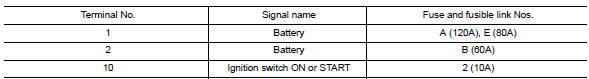
Is the fuse blown?
YES >> Replace the blown fuse or fusible link after repairing the affected circuit.
NO >> GO TO 2
2. CHECK BATTERY POWER SUPPLY CIRCUIT
1. Turn ignition switch OFF.
2. Disconnect IPDM E/R.
3. Check voltage between IPDM E/R connectors and ground.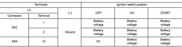
Is the measurement value normal?
YES >> GO TO 3
NO >> Repair or replace harness.
3. CHECK GROUND CIRCUIT
1. Turn ignition switch OFF.
2. Check continuity between IPDM E/R connectors and ground.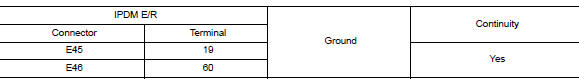
Does continuity exist?
YES >> Inspection End.
NO >> Repair or replace harness.
REMOVAL AND INSTALLATION
 B2099 Ignition relay off stuck
Description The ignition relay integrated in IPDM E/R is operated with ignition switch ON signal from the ignition switch. DTC Logic DTC DETECTION LOGIC Diagnosis Procedure 1. PERFORM SELF ...
IPDM E/R
Removal and Installation CAUTION: IPDM E/R integrated relays are not serviceable parts and must not be removed from the unit. REMOVAL 1. Disconnect the battery negative terminal. Refer to PG-6 ...
Other materials:
P072D Stuck in 2GR
DTC Logic
DTC DETECTION LOGIC
DTC
Trouble diagnosis name
DTC detection condition
Possible causes
P072D
Stuck in Gear 2
The following diagnosis conditions
are met and the detection
conditions continue for 0.5 seconds
or more.- Diagnosis condition
- Shiftin ...
Front seat
DRIVER SIDE
DRIVER SIDE : Exploded View
WITH REMOVABLE HEADREST
1. Armrest (if equipped) 2. Seat cushion outer finisher (RH) 3. Seat belt
buckle
4. Seat cushion trim 5. Seat cushion pad 6. Seat cushion frame
7. Seat cushion outer finisher (LH) 8. Lift lever (if equipped) 9. Lift lever
c ...
Categories
- Manuals Home
- Nissan Versa Owners Manual
- Nissan Versa Service Manual
- Video Guides
- Questions & Answers
- External Resources
- Latest Updates
- Most Popular
- Sitemap
- Search the site
- Privacy Policy
- Contact Us

0.0046