Nissan Versa (N17): IPDM E/R
Removal and Installation
CAUTION: IPDM E/R integrated relays are not serviceable parts and must not be removed from the unit.
REMOVAL
1. Disconnect the battery negative terminal. Refer to PG-63, "Removal and Installation".
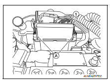
2. Remove the IPDM E/R cover.
3. Release the pawls (A) and separate the IPDM E/R (1) from the case.
4. Disconnect the harness connectors and remove the IPDM E/R.
INSTALLATION
Installation is in the reverse order of removal.
POWER DISTRIBUTION SYSTEM
 Power supply and ground circuit
Diagnosis Procedure Regarding Wiring Diagram information, refer to PCS "Wiring Diagram". 1. CHECK FUSE AND FUSIBLE LINKS Check that the following IPDM E/R fuse or fusible links are not bl ...

Other materials:
Door lock function
DOOR LOCK FUNCTION : System Description
SYSTEM DIAGRAM
DOOR REQUEST SWITCH OPERATION
When pressing the request switch, it is possible to lock and unlock the door
by carrying the Intelligent Key.
OPERATION DESCRIPTION
When the BCM detects that each door request switch is pressed, it s ...
Front fender
FRONT FENDER : Removal and Installation
CAUTION:
Use a shop cloths to protect the body from being damaged during removal and
installation.
REMOVAL
Remove fender protector. Refer to EXT "Removal and Installation".
Remove front bumper fascia and bumper side bracket. Refer to EXT
...
Categories
- Manuals Home
- Nissan Versa Owners Manual
- Nissan Versa Service Manual
- Video Guides
- Questions & Answers
- External Resources
- Latest Updates
- Most Popular
- Sitemap
- Search the site
- Privacy Policy
- Contact Us

0.0059