
Nissan Versa (N17): Rear
REAR : Exploded View
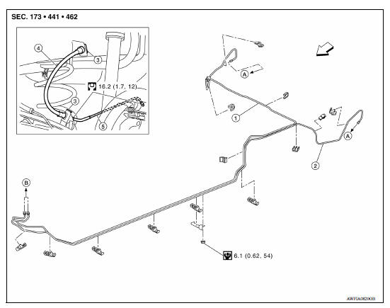
1. Rear brake pipe assembly (RH) 2. Rear brake pipe assembly (LH) 3. Lock
plate
4. Rear brake hose 5. Wheel cylinder brake pipe assembly A. To rear brake hose
B. To brake pipe connector  Front
Front
Rear : Hydraulic Piping
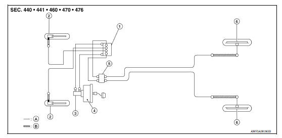
1. ABS actuator and electric unit (control
unit)
2. Front disc brake 3. Master cylinder assembly
4. Brake booster 5. Connector 6. Rear drum brake
A. Brake pipe B. Brake hose
 : Flare nut
 : Union bolt
CAUTION:
- All hoses and piping (tubes) must be free from excessive bending, twisting and pulling.
- Make sure there is no interference with other parts when turning steering both clockwise and counterclockwise.
- The brake piping is an important safety part. If a brake fluid leak is detected, always disassemble the parts. Replace applicable part with a new one, if necessary.
- Be careful not to splash brake fluid on painted areas; it may cause paint damage. If brake fluid is splashed on painted areas, wash it away with water immediately.
- Do not bend or twist brake hose sharply, or strongly pull it.
- When removing components, cover connections so that no dirt, dust, or other foreign matter gets in.
- Do not reuse drained brake fluid.
- After installation of the ABS actuator and electric unit (control unit), refill brake system with new brake fluid. Then bleed the air from the system. Refer to BR "Bleeding Brake System".
Rear : Removal and Installation
REMOVAL
CAUTION: Do not spill or splash brake fluid on painted surfaces. Brake fluid may seriously damage paint. Wipe it off immediately and wash with water if it gets on a painted surface.
NOTE: When removing components such as hoses, tubes/lines, etc., cap or plug openings to prevent fluid from spilling.
- Remove the wheel and tire assemblies using power tool. Refer to WT "Adjustment".
- Drain brake fluid. Refer to BR "Draining".
- Loosen the flare nut with a flare nut wrench and separate the brake pipe from the brake hose.
CAUTION:
- Do not scratch the flare nut and the brake pipe.
- All brake hoses and pipes must be free from excessive bending, twisting and pulling.
- Remove the lock plate and remove the brake hose from the vehicle.
- Loosen the flare nut with a flare nut wrench and separate the brake pipe from the wheel cylinder, and remove the brake pipe.
INSTALLATION
- Connect the brake pipe to the wheel cylinder, temporarily tighten the flare nut by hand until it does not rotate further.
- Connect the brake hose to the brake pipe, temporarily tighten the flare
nut by hand until it does not rotate
further, and fix the brake hose to the bracket with the lock plate.
CAUTION: Check that the brake hoses and pipes are not bent or twisted.
- Tighten the flare nut to the specified torque with a flare nut flare nut
torque wrench.
CAUTION: Do not scratch the flare nut and the brake tube.
- Refill with new brake fluid and perform the air bleeding. Refer to BR
"Bleeding Brake System".
CAUTION: Do not reuse drained brake fluid.
- Install the wheel and tire assemblies to the vehicle. Refer to WT "Adjustment".
- Perform inspection after installation. Refer to BR "REAR : Inspection".
Rear : Inspection
INSPECTION AFTER INSTALLATION
- Check the brake hoses and tubes for the following: no scratches; no
twist and deformation; no looseness
at connections.
CAUTION: Clearance with brake hose and each parts being secured more than 10 mm (0.39 in) in unladen condition*.
*: Fuel, engine coolant and lubricant are full. Spare tire, jack, hand tools and mats are in designated positions.
- Depress the brake pedal with a force of 785 N (80.1 kg-f, 176.5 lb-f)
and hold down the pedal for approximately
5 seconds with the engine running. Check for any fluid leakage.
CAUTION: Retighten the applicable connection to the specified torque and repair any abnormal (damaged, worn or deformed) part if any brake fluid leakage is present.
 Front
Front
FRONT : Exploded View 1. Master cylinder brake pipe assembly (front) 2. Master cylinder brake pipe assembly (rear) 3. ABS actuator to connector brake pipe assembly (RH) 4. ABS actuator to ...
Brake master cylinder
Exploded View 1. Reservoir cap 2. Brake fluid strainer 3. Reservoir tank 4. Grommet 5. Cylinder body 6. Brake fluid level switch 7. O-ring Apply brake fluid PBC (Poly Butyl Cuprysil) grease or ...
Other materials:
Precautions
Precaution for Supplemental Restraint System
(SRS) "AIR BAG" and "SEAT BELT PRE-TENSIONER"
The Supplemental Restraint System such as "AIR BAG" and "SEAT BELT PRE-TENSIONER",
used along
with a front seat belt, helps to reduce the risk or severity of injury to the
driver and ...
U0155 Lost communication (IPC)
DTC Logic
DTC DETECTION LOGIC
DTC
Trouble diagnosis name
DTC detection condition
Possible causes
U0155
Lost Communication With Instrument
Panel Cluster (IPC)
Control Module
When the ignition switch is ON,
TCM is unable to receive the
CAN communications ...
Categories
- Manuals Home
- Nissan Versa Owners Manual
- Nissan Versa Service Manual
- Video Guides
- Questions & Answers
- External Resources
- Latest Updates
- Most Popular
- Sitemap
- Search the site
- Privacy Policy
- Contact Us

0.0065