Nissan Versa (N17): Power supply and ground circuit
BCM (Body control system) (with intelligent key system)
BCM (BODY CONTROL SYSTEM) (WITH INTELLIGENT KEY SYSTEM) : Diagnosis Procedure
Regarding Wiring Diagram information, refer to BCS "Wiring Diagram".
1.CHECK FUSES AND FUSIBLE LINK
Check that the following fuses and fusible link are not blown.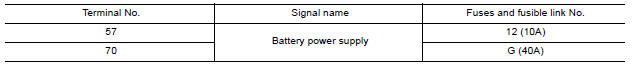
Is the fuse blown?
YES >> Replace the blown fuse or fusible link after repairing the affected circuit.
NO >> GO TO 2.
2.CHECK POWER SUPPLY CIRCUIT
1. Disconnect BCM connector M99.
2. Check voltage between BCM connector M99 and ground.
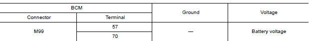
Is the inspection result normal?
YES >> GO TO 3.
NO >> Repair harness or connector.
3.CHECK GROUND CIRCUIT
Check continuity between BCM connector M99 and ground.

Is the inspection result normal?
YES >> Inspection End.
NO >> Repair harness or connector.
BCM (Body control system) (without intelligent key system)
BCM (BODY CONTROL SYSTEM) (WITHOUT INTELLIGENT KEY SYSTEM) : Diagnosis Procedure
Regarding Wiring Diagram information, refer to BCS "Wiring Diagram".
1.CHECK FUSES AND FUSIBLE LINK
Check that the following fuses and fusible link are not blown.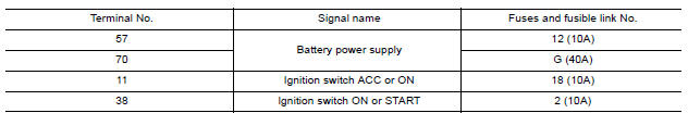
Is the fuse blown?
YES >> Replace the blown fuse or fusible link after repairing the affected circuit.
NO >> GO TO 2.
2.CHECK POWER SUPPLY CIRCUIT
1. Turn ignition switch OFF.
2. Disconnect BCM connectors.
3. Check voltage between BCM connector and ground.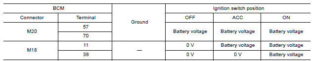
Is the inspection result normal?
YES >> GO TO 3.
NO >> Repair harness or connector.
3.CHECK GROUND CIRCUIT
Check continuity between BCM connector and ground.
Is the inspection result normal?
YES >> Inspection End.
NO >> Repair harness or connector.
Power window main switch
POWER WINDOW MAIN SWITCH : Diagnosis Procedure
Regarding Wiring Diagram information, refer to PWC "Wiring Diagram".
1.CHECK POWER WINDOW MAIN SWITCH POWER SUPPLY
1. Turn ignition switch OFF.
2. Disconnect power window main switch connector.
3. Check voltage between power window main switch harness connector and
ground.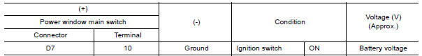
Is the inspection result normal?
YES >> GO TO 3.
NO >> GO TO 2.
2.CHECK POWER WINDOW MAIN SWITCH POWER SUPPLY CIRCUIT
1. Turn ignition switch OFF.
2. Disconnect BCM connector.
3. Check continuity between BCM harness connector and power window main
switch harness connector.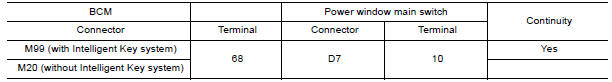
4. Check continuity between BCM harness connector and ground.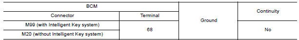
Is the inspection result normal?
YES >> Replace BCM. Refer to BCS "Removal and Installation".
NO >> Repair or replace harness.
3.CHECK POWER WINDOW MAIN SWITCH GROUND CIRCUIT
1. Turn ignition switch OFF.
2. Check continuity between power window main switch harness connector and
ground. 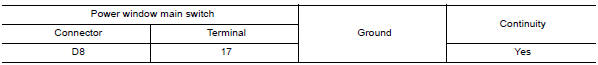
Is the inspection result normal?
YES >> Inspection End.
NO >> Repair or replace harness.
Front power window switch (passenger side)
FRONT POWER WINDOW SWITCH (PASSENGER SIDE) : Diagnosis Procedure
Regarding Wiring Diagram information, refer to PWC "Wiring Diagram".
1.CHECK FRONT POWER WINDOW SWITCH RH POWER SUPPLY
1. Turn ignition switch OFF.
2. Disconnect front power window switch RH connector.
3. Turn ignition switch ON.
4. Check voltage between front power window switch RH harness connector and
ground.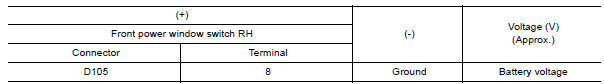
Is the inspection result normal?
YES >> Inspection End.
NO >> GO TO 2.
2.CHECK FRONT POWER WINDOW SWITCH RH POWER SUPPLY CIRCUIT
1. Turn ignition switch OFF.
2. Disconnect BCM connector.
3. Check continuity between BCM harness connector and front power window
switch RH harness connector.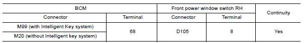
4. Check continuity between BCM harness connector and ground.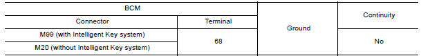
Is the inspection result normal?
YES >> Replace BCM. Refer to BCS "Removal and Installation".
NO >> Repair or replace harness.
Rear power window switch
REAR POWER WINDOW SWITCH : Diagnosis Procedure
Regarding Wiring Diagram information, refer to PWC "Wiring Diagram".
1.CHECK REAR POWER WINDOW SWITCH POWER SUPPLY
1. Turn ignition switch OFF.
2. Disconnect rear power window switch connector.
3. Turn ignition switch ON.
4. Check voltage between rear power window switch harness connector and
ground.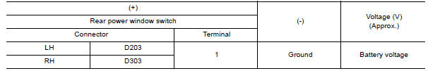
Is the inspection result normal?
YES >> Inspection End.
NO >> GO TO 2.
2.CHECK REAR POWER WINDOW SWITCH POWER SUPPLY CIRCUIT
1. Turn ignition switch OFF.
2. Disconnect BCM connector.
3. Check continuity between BCM harness connector and rear power window
switch harness connector.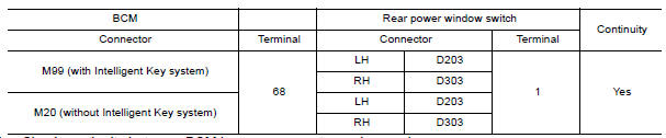
4. Check continuity between BCM harness connector and ground.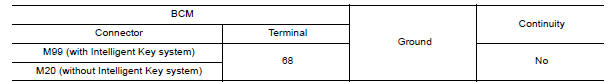
Is the inspection result normal?
YES >> Replace BCM. Refer to BCS "Removal and Installation".
NO >> Repair or replace harness.
 Diagnosis and repair work flow
Work Flow OVERALL SEQUENCE DETAILED FLOW 1. OBTAIN INFORMATION ABOUT SYMPTOM Interview the customer to obtain as much information as possible about the conditions and environment under whi ...
Front power window switch (passenger
side)
Component Function Check 1. CHECK FUNCTION Check front power window motor RH operation with front power window switch RH. Is the inspection result normal? YES >> Inspection End. NO >> ...
Other materials:
Control panel buttons - color screen with Navigation System (if so equipped)
WARNING
Positioning of the heating or air conditioning
controls and display controls
should not be done while driving in order
that full attention may be given to
the driving operation.
Do not disassemble or modify this system.
If you do, it may result in accidents,
fire, or elec ...
Mainshaft and gear
Exploded View
1. Mainshaft front bearing 2. Mainshaft 3. 1st main gear
4. 1st inner baulk ring 5. 1st synchronizer cone 6. 1st outer baulk ring
7. 1st-2nd synchronizer hub 8. 1st-2nd coupling sleeve 9. Spring
10. Insert key 11. 2nd outer baulk ring 12. 2nd synchronizer cone
13. 2nd inner b ...
Categories
- Manuals Home
- Nissan Versa Owners Manual
- Nissan Versa Service Manual
- Video Guides
- Questions & Answers
- External Resources
- Latest Updates
- Most Popular
- Sitemap
- Search the site
- Privacy Policy
- Contact Us

0.0101